
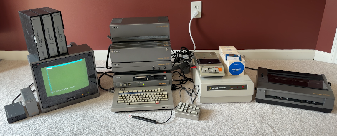
The Sony SMC-70 (Sony Micro Computer, is that a bit like saying ATM Machine?) was my first computer. It’s anyone’s guess what the 70 represented. In 1980, Sony announced the Series 35 word processor, the first device to use their new 3.5″ floppy drive. 35 was chosen as the model number not because of the new floppy drive, but because the year the system was released, 1981, was Sony’s 35th anniversary. It’s possible with 7 being a lucky number in Japan, they just doubled the model number of the word processor. Incidentally, in a nod to this machine, when Sony reentered the PC business in 1996, their first model was the VAIO PCV-70 (Personal Computer Video), a system with a Pentium 166. The number 7 popped up a lot in machines from Japan in the 80s, including the Casio FP-7000, Epson HC-7, Fujitsu FM-7, Hitachi 70 Series, NEC PC-7001, Sanyo PHC-77 and PHC-70FD, Sharp MZ-700, and Toshiba Pasopia 7 and 700 (none were released before the SMC-70). Japanese computer manufacturers really liked the number 7!
The SMC-70 was both ahead of, and behind the times when it was released in 1982. It was a color Z80-based system running CP/M at a time when not only color CP/M systems were rare, but color was rare in the computer industry. The Z80A, the processor inside the SMC-70, was released 5 years earlier in 1977, one year after the release of the original 2.5 MHz Zilog Z80, while CP/M 2.2 was released 2 years earlier in 1980. Things were moving quickly in the early 80s. The 16’ish bit IBM PC was released the previous year in August 1981 and was now considered the benchmark for business computers, the market Sony was trying to enter. It was an odd time for Sony, as they were still developing word processors in parallel with the SMC-70, including a word processor that could run CP/M as an option, and therefore much of the same library of CP/M software as the SMC-70.
Color was what set the system apart. IBM’s CGA adapter, available in the Model 5150, could display 16 colors at 320×200, and 2 colors at 640×200. The SMC-70 was also capable of displaying 16 colors at 320×200, but could display 4 colors at 640×200, and monochrome graphics at 640×400. The system had better color graphics than CGA, a higher monochrome resolution than MDA, and users didn’t have to make a choice between the two. Like other color palettes of the time, the colors of the rainbow weren’t available, and there wasn’t a palette of colors to select from (this would come later as an option with the home-oriented model Sony released a year later in Japan, the SMC-777), but Sony didn’t offer the standard CGA color palette either. The colors available were black, ash blue, dark green, deep blue, red, bright green, salmon, yellow, gray, light blue, moss green, turquoise, pale pink, brilliant pink, tan, and white.

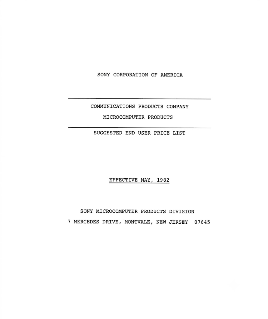
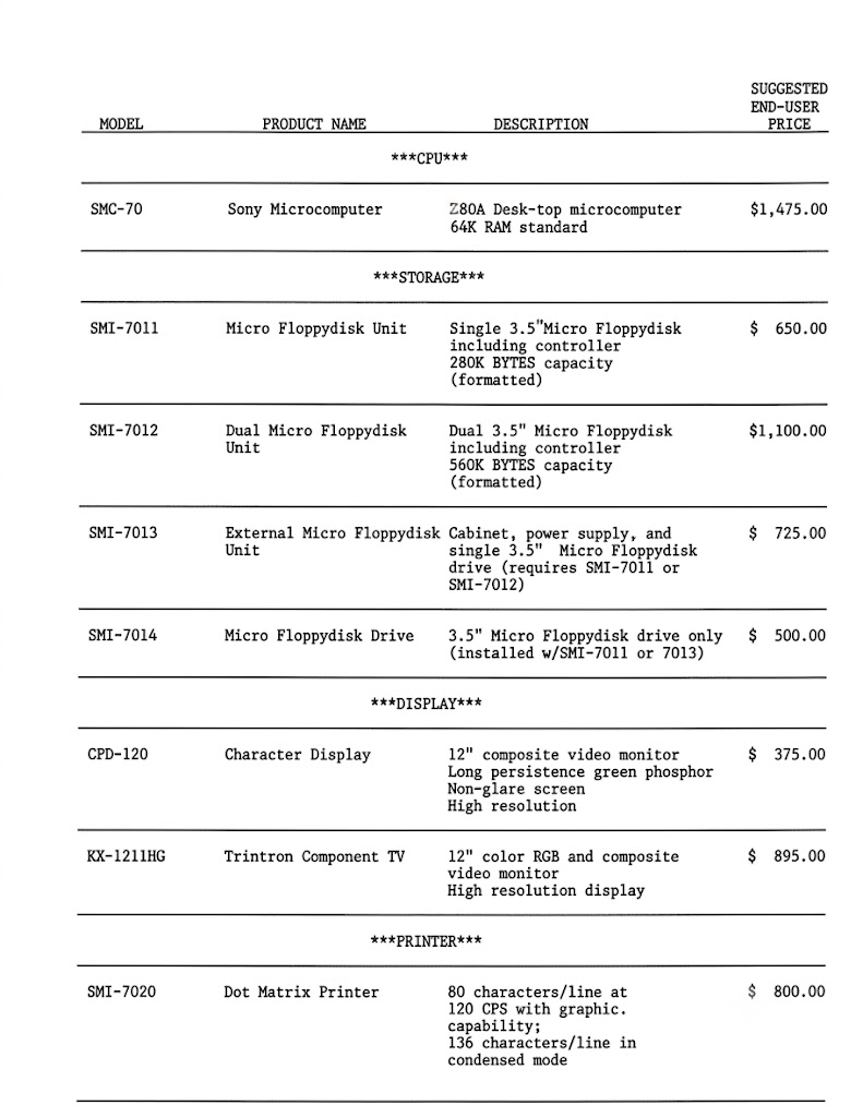
At an announcement on May 17, 1982, Sony stated a list price of $1,475 for the SMC-70, which would fall to $995 by January 1984. The New York Times covered the announcement. The SMC-70G was announced on September 29, 1983 with a suggested retail price of “under $3,000”. Buying a computer in 1982 wasn’t like buying a computer today, so while that $1,475 purchased a capable machine, there wouldn’t have been much someone could have done with the machine other than make it beep! That purchase price didn’t include any floppy drives (or floppy drive controller), a monitor, or a cassette recorder. But the SMC-70 did come with built-in hardware that an IBM PC did not, including a serial port, parallel port, color and monochrome video, 48K of additional system RAM, a real-time clock, and light pen support. Users were expected to configure both systems to meet their needs, Sony just included a bit more value for the money. Other options were similar between the two machines, such as a cassette port, and instead of a keyboard port, the SMC-70 had a port for an optional numpad. Considering this was sold as a business machine, the numpad being optional was seen as an odd choice by Sony, but it’s possible they expected many users to buy the machine for word processing.
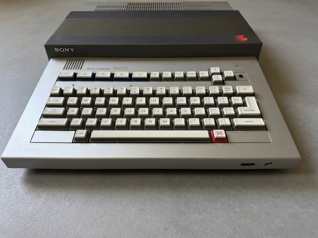
So, the second obvious purchase after the base machine would be a monitor.
What perhaps sets the SMC-70’s color capabilities apart from the few other color CP/M machines on the market was the Sony Trinitron monitor. While a 12″ long persistence green phosphor monitor with a built-in speaker was available (the Sony CPD-120) with a list price of $375 (often available for $280), the system was typically paired with the 12″ Trinitron KX-1211HG which had a list price of $895. Oddly, the monitor was named the KX-13HG1 and listed as a 13″ monitor in Japan, with a list price of $650 (after conversion). The monitor had a 0.39mm dot pitch, accepted both composite and RGB (analog or TTL) signals, and had a 15kHz horizontal and 60Hz vertical scan range. It had handy (and sturdy) carrying handles on top, screw holes on the side to mount optional speakers, and a removable tinted glass front panel that improved the contrast but had to be removed to use the optional light pen (SMI-7061; $175).
For those with deeper wallets, the PVM-1270Q/1370QM, released in 1983, was a later option, with a 0.25mm dot pitch and a list price of ~$950. This monitor was an option for, and often paired with, the SMC-70G. The cable to connect the computer to the monitor was another $55 for the KX monitors (SMK-0001) and $90 for the PV monitors (SMK-0002).
By spending $2,425, a user could buy a computer with a color monitor and the cable to connect the two that included Sony’s System Monitor and Sony BASIC in ROM. There still wouldn’t be much users could do with the system unless they wanted to type in a new program every time they started the system, assuming they knew how to write those programs!
If a user actually wanted to know how to use the computer and software, that would cost even more! The Micro Computer Operating Instructions (SML-7000) cost $12; one was supposed to be included with the system (though some of my systems only contained the computer and packing material), the Sony BASIC Introductory Manual (SML-7001) was $20, the Sony BASIC Programming Reference Manual (SML-7002) was $20, the System Monitor Reference Manual (SML-7003) was $25, and the Hardware Reference Manual (SML-7004) cost $20. In Japan, the prices were higher ($13, $28, $33, $43, and $37, respectively). While the prices may seem high, Sony was widely praised for the quality of their documentation, with the extensive documentation touted in the press as a reason to consider buying the system in the first place.
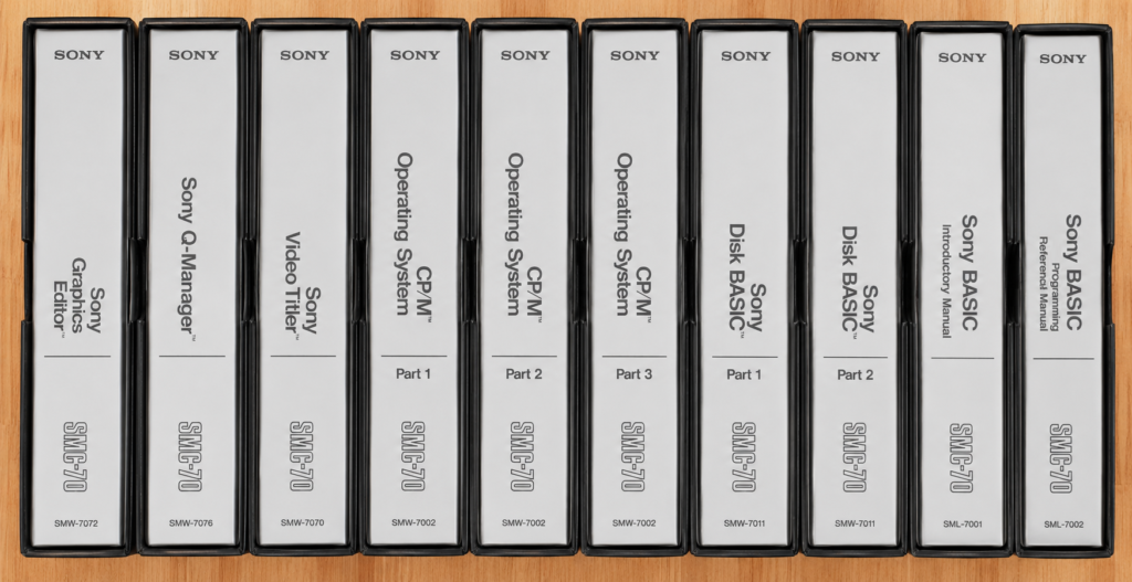
In the US, the manuals came in a 3-ring binder in a black sleeve, and each manual included a disk holder to store the master copy of the software. In Europe the storage sleeves were gray. In Japan 2-ring binders were available, but the documentation typically wasn’t the same loose-leaf paper that was available elsewhere; users were usually putting the bound paper manuals into a binder (a couple of loose leaf manuals existed, including a CP/M System Disk Explanation manual, which was a fraction of the size of the US CP/M manuals, and a SuperCalc manual). Those binders were stored in black sleeves like in the US.
The manual model numbers ended with a Z to indicate they included the binder (e.g., SML-7002Z; you’ll notice in the picture that some of the manuals reference the part number of the software, while others have the part number of the manual). You might also be noticing as you read that almost everything for this system has a part number, and almost all of them start with SM (Sony Micro), followed by another letter. For example, SML stood for literature (though it wasn’t consistently used, as mentioned, many manuals used the same part number as the underlying software), SMI for interface unit, SMW for software, SMD likely for device, SMK likely standing for konpyūta akusesari, the Japanese word for computer accessory, or kēburu the Japanese word for cable; K was used for all of the cables and a couple of accessories, including the monitor stand and expansion module cases. There was also an SMC-70K that was released in Japan, though the K does not have the same meaning in this context. SMF was also used for all 500 series cables (SMF-500 to 506).
Other identifiers included SMJ-E for Japanese educational software, SMJ-G for Japanese game, SMJ-S for Japanese software, SMU for utility software, SMW-E for software educational, and SMW-G for software game and SMJ-xxxB for Japanese Book. SMW-H also existed for software home & hobby, but software under this category appears to have only been released for the SMC-777.
Sony’s model, release, and versioning scheme wasn’t always exactly clear. For example, Metasoft’s Letterwriter was SMW-7045, but this wasn’t noted on the disks. The disk is labeled as version 1-A, while Sony referred to it as version 1.0. The title screen indicated it was LetterWriter 2.0. For part numbers, an A meant it was the second release of a product (e.g., the SMI-7011A was the internal floppy drive expansion that was populated with only one drive, but it was the second revision that included the ability to work with auto shutter disks). But for software, version 1-A was the first release, and 1-B was the second. When it came to PAL software, all of the labeling rules went out the window!
Games released in Japan didn’t follow this pattern, which ended in D (for disk). C is the furthest software revision I have seen. D was used on a software release, Graphics Editor, but in this case it meant that version supported a digitizer (though most non-D versions support it one as well). K and L were only used once to distinguish two different software titles with the otherwise same part number (SMW-7040K, Sony Japanese Word Processor and SMW-7040L Sony EZ Report); both programs are nearly identical. Lastly, P (and PE/PD) was sometimes used as a prefix and a suffix for PAL systems and software, such as for Q-Manager (SMW-P7076), Video Titler (SMW-PE7070), and the PAL Superimposer (SMI-7074P). The E and D referred to the language, English or German (Deutsche).
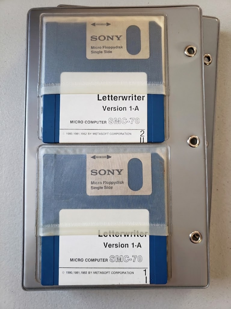
The Word Processor had at least 3 releases, with SMW-70461-B being version 1-B but listed as Word Processor 3.0K, and SMW-70461-C being version 1-C but listed as Word Processor 3.0M, yet the W/P Mathpack had 2 releases, with SMW-7049 version 1-A being listed as W/P Mathpack Ver 3.0K, and SMW-7049 version 1-B listed as W/P Mathpack Ver 3.0M. Part of the reason for this mess was because there was the Sony version and the vendor version.
The computer (and software) didn’t come with a copy of the CP/M operating system (though Sony did start to bundle it in later years). CP/M 2.2 Release 1.0 was the initial release for the system (SMW-7002) and retailed for $150. Known versions include releases 1.0, 1.0J, 1.1, 1.1J, 1.2, 1.2GP, 1.2J, 2.0, and 2.1. While I would think there should be a 2.0J version, oddly I haven’t seen evidence of it, nor a 2.0 PAL version. Version 1.2 is the first version with support for the SMC-70G. Without a copy of CP/M, it’s not possible to do anything with software disks. One of the first instructions in any software manual was to make a copy of the disk, and make that copy bootable using a copy of CP/M. Because of the price of software Sony never wanted users to work with the original copies!
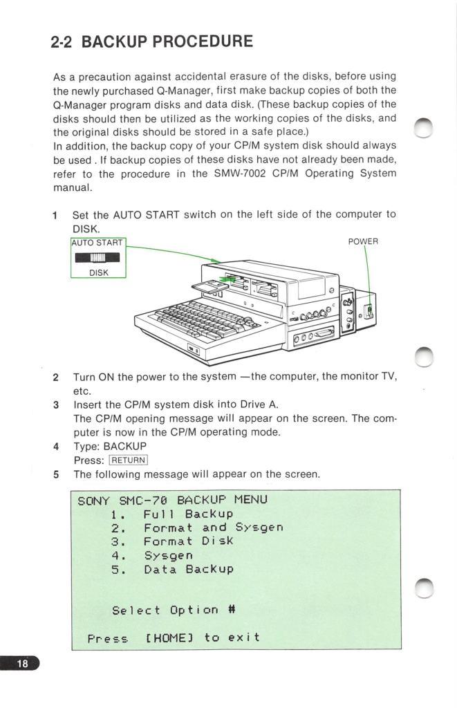
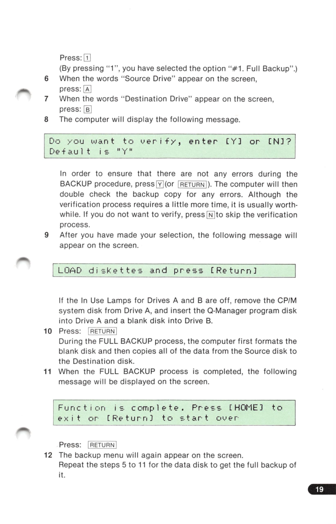
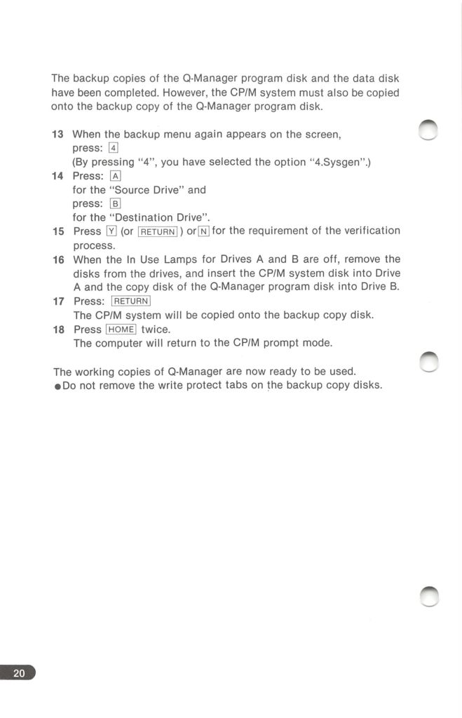
Some programs offered their own installation utility, and Sony recommended keeping the application on one disk and files on another. Here is a short video of the drives in action installing SSG’s General Ledger:
The 3.5″ floppy drives that were available as an option on the SMC-70 were another thing that set it apart from other systems on the market. The development of the 3.5″ floppy drive by Sony began in late 1979, but it’s not quite the same floppy drive that was widely used in computers around the world. In some ways, Sony’s was both better and worse. Sony’s drive had the same transfer rate as a double density 8″ drive at 500 kbps, giving it twice the transfer rate of both 5.25″ and modern 3.5″ drives. It did this by spinning at 600 RPM, twice the speed of a standard 3.5″ floppy drive. One of the side effects of this high rotational speed was a lower latency of 50ms compared to 100ms of a typical 3.5″ or 5.25″ floppy drive. Prior to the release of Sony’s drive, 5.25″ drives had a transfer rate of 250 kbps; and this is ultimately the reason today’s floppy drives spin at 300 RPM. The industry wanted future 3.5″ drives to be backward compatible with existing 5.25″ drive controllers so manufacturers wouldn’t have to create new hardware. There were a few other differences as well. One major one that impacted compatibility between Sony’s existing 3.5″ media at the time and newer drives was the coercivity or magnetic strength with which the data is written to the disk.
Sony’s original manual shutter disks stored data using a lower coercivity magnetic coating than modern disks, though the specific magnetic strength isn’t clear. One source says it was 500 oersteds, another gives 580 Oe, while a third gives 550 Oe, the same as Betamax. The coating is 2.54 microns thick. Modern drives error out when attempting to read this media as the magnetic field is too weak, which limited the ability of users to transfer files stored on these disks to other systems (modern tools like a Greaseweazle or KryoFlux that control the drive at a hardware level can be used to image these disks). The Microfloppy Industry Committee compromise for magnetic strength was 625 Oe, while in practice double density disks (720KB) store data using a disk magnetic coating that’s 650-665 Oe and 2 microns thick, and high density (1.44MB) disks use a coating with a field strength of 720-750 Oe that’s 1.2 microns thick.
Another major difference was the media used 70 tracks instead of 80, which gave the disks an unformatted capacity of 437.5KB, and 280KB formatted (the formatted capacity depends on the file/operating system). The original drives were single sided. With each track storing 6.25KB, 80 tracks would provide 500KB of storage per side, or 1MB per disk, which was what eventually became the standard. It’s possible to replace an existing drive in the system with either the Sony OA-D32V or OA-D32W, and with a modified version of CP/M, the SMC-70 could access all 80 tracks on a disk.
Releases 2.0 and 2.1 of Sony’s CP/M partially support the double-sided drive as well, but the support is half-baked. The backup utility will format tracks 0-69 on side one, and then tracks 0-69 on side 2, but will fail to sysgen (install the bootloader), nor can it do the track-to-track backup of a disk. If using the newer drives to only read files, a consequence of this modification is the newer drives cannot read manual shutter media with the weaker magnetic field.
For anyone who wants to archive Sony disks that are on manual shutter disks without any special hardware, the best way to do it is to copy the disk to an auto shutter (or modern) disk, and then archive this disk using a program like IMD in DOS. Sony’s backup utility will make a track-by-track copy of the original disk. Sony software did not have copy protection.
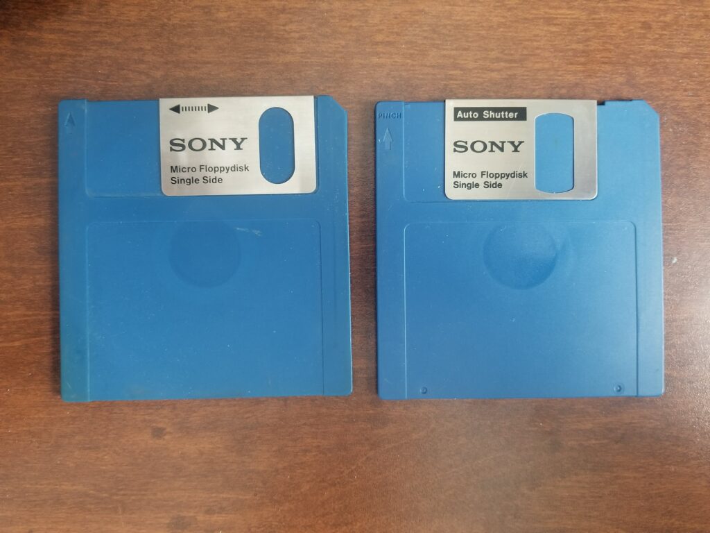
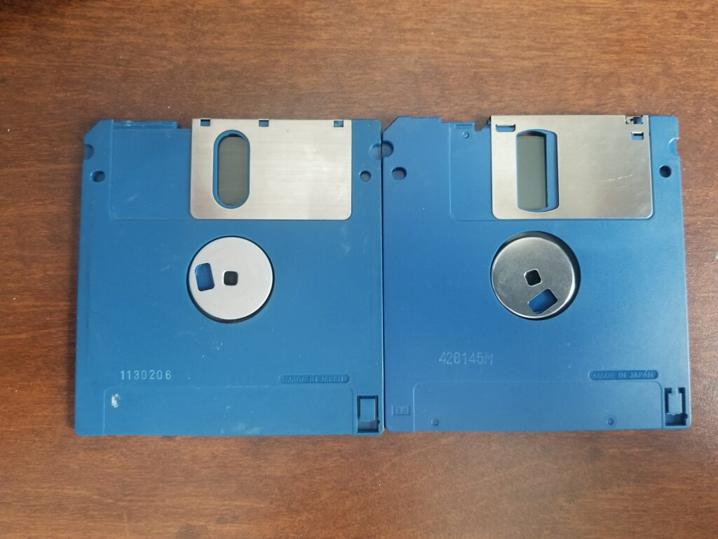
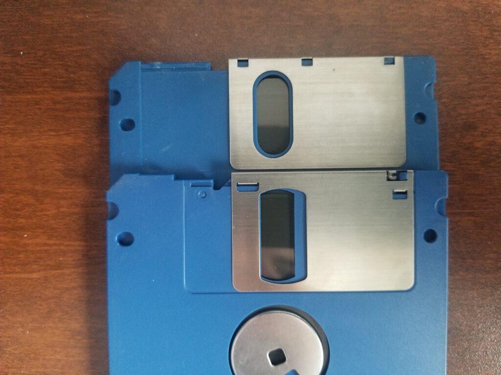
The final difference between Sony’s standard and modern disks was that Sony did not include an auto shutter, or spring-loaded disk shutter. On the original Sony disk, the OM-D3310 (Office Media), the user was required to manually open the disk shutter before inserting the floppy disk into the drive. After ejecting the disk, the shutter had to be manually closed.
The first product to use the newly developed 3.5″ drive was Sony’s WYSIWYG word processor announced in December 1980 and released in 1981, the Series 35 (OA-S3300, OA standing for Office Automation). The news of the floppy drive was a bigger deal than the word processor! Their second product to use the drives was the SMC-70. The SMC-70 optionally shipped with the SMI-7011 or SMI-7012, which was an expansion unit that housed either one or two model OA-D30V drives (single sided), at a price of $650 for a single drive and $1,200 for two. The unit included the floppy drive controller, which was installed inside the unit to the left of the drives, and connected to one of the two available expansion slots in the SMC-70. The floppy drive expansion contained the system’s only fan and cooled the controller.
There was an external floppy drive expansion that also allowed for up to two additional 3.5″ drives to be installed (SMI-7013) at a price of $725; it included a single drive. This expansion connected to the disk controller in the SMI-7011/7012 via a DE25 connector. This was an incredibly rare accessory, as there wasn’t much of a reason for someone to have more than two floppy drives connected to a single system. Note that 5.25″ and 8″ drives could not be connected to the 3.5″ floppy controller, there was another accessory for connecting those drives.
The price for a bare drive (SMI-7014) itself was $500, which could be added as a second drive to the SMI-7011 (the internal unit) or the fourth drive to the SMI-7013 (the external unit). A short time later the SMI-7011A/7012A/7013A/7014A started shipping, which changed the drive to a model OA-D31V/MFD-31V drive. This drive included the ability to open the disk shutter. In Japan, the March 1983 catalog listed the manual shutter drives, while the April 1983 catalog was updated to show the auto shutter models, showing when the transition likely occurred.
When Sony decided to sell their drives to others, it was thought that they would face an uphill battle with the 3.5″ drive. For starters, internally, Sony’s policy was that they did not sell their products to OEMs, so the only place for a Sony drive would be a Sony device. Another issue was that there were a number of competing ~3″ floppy standards being introduced (though Sony’s was the first), some by established companies, and at the time Sony was not a manufacturer of 5.25″ or 8″ floppy drives, nor were they in the computer business. But Sony was quite familiar with magnetic media, as they were a leader in broadcasting, which was what led them to create the drive in the first place. Sony’s offering was also superior in many ways to both existing formats and the new formats that were popping up. Perhaps their most important advantage in the ~3″ battle was storage capacity.
By September 1983 an estimated 50,000 3.5″ drives had been sold, 25,000 of them by HP. To put that in perspective, according to Sony, they produced a little over 5,000 drives in 1982. By the end of 1983 that number climbed to 140,000 drives shipped. While Sony holds the honor of creating both the first device and the first computer with a 3.5″ floppy drive, they were not the first to get their computer to market. Sony had development models of the computer in 1981 and waited months after finalizing it before releasing it to ensure they had a dealer network in place to sell and service the system before making it available to customers.
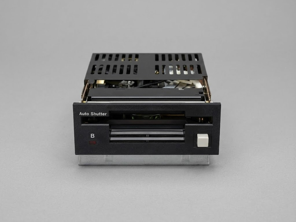
Software was shipped on both manual and auto shutter media, and as mentioned, Sony was quick to release a drive that supported this new auto-shutter design, and they offered retrofit kits for existing drives, making manual shutter drives somewhat rare to find. Drives with the mechanism to open the shutter often say “Auto Shutter” on them, unless the retrofit was installed. This labeling was unique to Sony, other manufacturers used blank drive faceplates. Sony also had a little indent above the drive in-use LED for a sticker to indicate the drive letter that other manufactures did not include.
Sony had to make media with a locking shutter for some time to be backwards compatible with drives that did not have the retrofit applied, though only the OA-D30V and OA-D31V could read the first generation of media (OM-D3310) as mentioned above. Because the auto shutter media (OM-D3320) had the locking shutter, many users thought they had to manually lock the shutter before inserting it into the drive, negating the entire purpose of the auto shutter! It could have been out of habit because they had to do it for some disks, so they did it with all disks. Disks were sold in 10 packs at a price of $5 per disk ($17.86 a MB), which is around $17 a disk in 2026, and $68 a MB.
Being this cutting edge wasn’t necessarily a good thing; while history shows Sony was the victor in the floppy format war, this wasn’t assured, and we know they didn’t have as much luck with Betamax, Memory Stick, and MiniDisc (though MiniDisc was popular in Japan). Because it was a new disk format, it was difficult for users to get new software and exchange software and data with other computer users who were using 5.25″ drives into the early 90s. But this history of creating media formats was what got Sony into the computer business in the first place. While so much of their system was cutting edge, one thing that really stood out in 1982 as not being terribly cutting edge was their reliance on CP/M.
Sony officially debuted the computer at the June 7th National Computer Conference in Houston, Texas in 1982. Like IBM a year earlier, the industry was expecting Sony to enter the market (it wasn’t exactly a secret they were building a computer). The industry was just expecting them to enter the market with a 16-bit computer. What was hyped at the launch was that the system would interface with video disk readers (and recorders) when commercially available, but details were scarce.
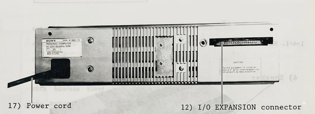
The technical documentation of the SMC-70 shared with dealers was nearly finalized by July of 1982. In a typo-ridden preliminary technical training manual published that month, the company left blank the power supply wattage in a specifications section, but a picture of a prototype unit showed a 60-watt power supply (this is likely the amount available to accessories, as production units have a 114-watt power supply, though just 65 watts is available for peripherals, a number shown on the rear of Japanese systems, but not those released in western markets, which show voltage and amps) and the 50-pin rear I/O expansion had an IDC connector, not a micro ribbon (aka 50-pin Amphenol or Centronics) connector. The system was also labeled as a Personal Computer on both the rear label and above the keyboard, which Sony later changed to Micro Computer.
For anyone keeping track, the running total for a PC with monitor, monitor cable, disk drives, operating system, manuals, and a pack of disks would run $3,760. A dot matrix printer, cable, and monitor stand (SMI-7020; $800, SMK-0020; $60 & SMK-0091A or SMK-0091B; $60) would bring the total to $4,680. This was a competitive price. The IBM PC cost $4,540 for a system with the same 64KB of RAM, a single 5.25″ floppy drive, a CGA card with CGA monitor, and PC-DOS. The Sony also includes a real-time clock with battery backup. Incidentally, the original NiCad batteries still work on all of my systems, but if you own one, it’s worth checking the battery in your system to ensure it isn’t leaking. Sony was smart enough to put it in a location where it wouldn’t do much damage if it were to leak. Like most systems of the era, the clock is not Y2K compliant. Both companies offered options to expand their respective systems, though Sony’s method was much easier.
The SMC-70 had 2 internal expansion ports, 3 external expansion slots, and a rear port to allow additional expansion options, including an expansion unit, the SMI-7040 ($575) which provided 5 additional slots. Since the video, serial, and parallel ports were built into the SMC-70, they did not tie up expansion ports like those options did on the IBM 5150.
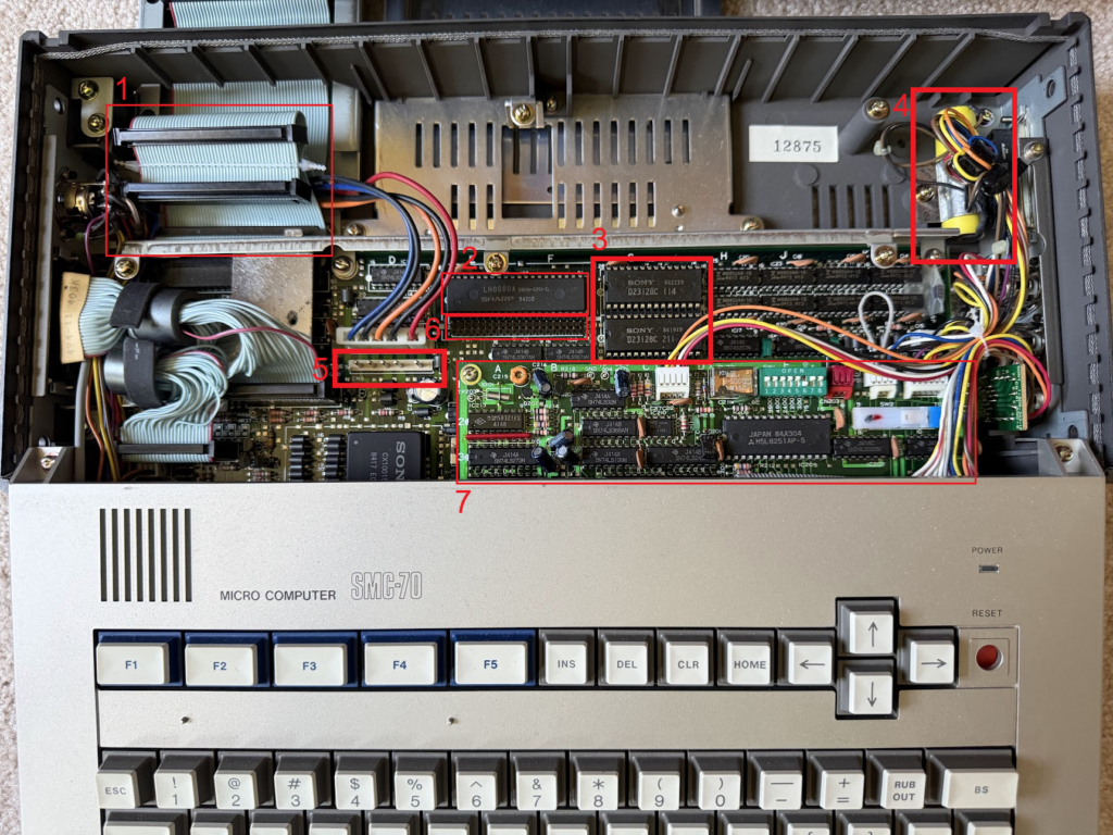
- 1. Internal expansion ports
- 2. Sharp Z80A processor
- 3. 2 128kbit (16KB) system ROM chips
- 4. RTC battery
- 5. Power connector for the battery backup (SMI-7080)
- 6. Diagnostic port/Possible 50-pin expansion for 192K Bank RAM (SMI-7051)
- 7. 19,200 baud serial adapter and cassette controller
One internal expansion port was almost always used for the 3.5″ disk controller. The second could be used for a variety of upgrades, though, in practice, in most markets the second slot rarely saw any use. In Japanese systems the second slot was always used for a ROM board with 6 sockets.
The SMC-70 had a limited Japanese launch 3 months after the US launch (it was available in 3 cities, based on advertisements, it had wider availability around May 1983). Due to intense competition in Japan, they sold it at a lower cost than in the US, selling it the base system for ¥228,000, which at the time was worth ~$980, a discount of $495. Production plans in Japan were based on initial US sales reports of 1,000 units a month (Sony was selling the system at 60 US retail outlets at the beginning of 1983). The system was to generate $20 million in sales for Sony for 1983, with a production target of 100,000 units a year “in two years or so”. Sony’s total revenue in 1983 was $3.4 billion. It’s safe to say sales numbers never came anywhere near the target.
Western market SMC-70/G units had 2 16K ROM chips on the motherboard that included System Monitor and Sony BASIC. Asian market systems needed to support basic kanji characters, and there wasn’t enough free space in the 32K of ROM to do this, so a daughterboard was the solution. The system ROM was recompiled into a single 16K ROM and kept on the motherboard, and then System Monitor, Sony BASIC, and the expanded character set were stored in two additional 16K ROM chips on the expansion board.
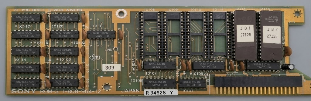
The ROM card had 4 open sockets, which could accept an optional kanji ROM kit. The kanji ROM kit was consisted of four ROM chips (SMK-0052/SMI-7052; $174). It included around 3,000 16×16 dot characters (JIS level 1). As these weren’t for the US market (western market systems didn’t have the ROM card that permitted them to be installed), there’s not any US literature on them. Note that a Japanese system would not have room (an open expansion port) with floppy drives installed to install the bank RAM card, which may be one reason it wasn’t released (more on this later).
The processor in the SMC-70 wasn’t quite standard, it was a Sharp Z80A that ran at 4.028 MHz, which might seem oddly specific. The reason this was selected was because it’s exactly 256 times the horizontal synchronization signal of NTSC (15.734kHz), which eliminated the need for any sort of complex circuitry to eliminate flicker when using the superimposers or genlocker.
Variations
Sony sold many variations of the SMC-70. The base SMC-70 was sold with various power supplies (100v, 120v, and 240v), keyboards, and ROM options depending on the country where it was sold. It seems that Sony did not sell the SMC-70 in many European countries, but did sell the SMC-70GP in later years (1984+), which may also partly explain why many believe the system wasn’t a general purpose computer.
Sony also released an SMC-70K in Japan, though there is no information about what the K stood for in this context (there is no information about this model in general). The serial number range for this variant appears to begin at 60,000 while the SMC-70 and the SMC-70G both began at 10,000. It is possible the K stood for kana, as the system’s keyboard had a JIS X 6002 standard kana layout, whereas the Japanese SMC-70 and SMC-70G both followed the Gojūon (fifty sounds) kana layout, which is roughly analogous to alphabetical order. Both Japanese keyboards had 73 keys, one more than western keyboards (the extra key was a kana lock key next to the help key).
The SMC-70G was made for NTSC markets, and was sold with both various power supplies, keyboards, and ROM options. Some magazines announced it in their August 1983 issues (a dealer, Electo Office in Japan, had an ad for it in Micro Monthly), but Sony officially announced it in September. Although the SMC-70G’s motherboard is almost identical to the SMC-70’s, there is a slight difference to accommodate the routing of video signals to the genlocker hardware which prevents swapping motherboards between the two systems.
For PAL markets, there was an SMC-70GP. The serial numbers for these systems start at 30,000, while much of the software for PAL systems starts at serial 3,000, instead of serial 1,000. What is interesting about the SMC-70GP is that it didn’t ship with ROM BASIC. This model shipped with a single 16KB ROM installed. Sony released a PAL version of CP/M that included a font utility that would allow a user to select ASCII, ASCII bold, UK, UK bold, German, or German bold to overwrite the character font loaded from ROM. Some SMC-70GP keyboards had stickers on the keys for special characters (such as ä).
Semi-External Expansion Options
Most users would use the external I/O expansion slots to expand the system. On the SMC-70 there were 3 available slots, the SMC-70G had 4. As you may notice in the picture of the internal and external PCBs, they look similar. Sony made it so it was possible to remove an external card from its case and install it internally (under the disk drives) in the system. This wasn’t useful with most cards, since they required a way to connect cables to an external device. But a few modules, like the ROM expansions and disk cache did not require any external connections.
With the external expansion unit that plugged into the rear of the unit (SMI-7040; $575), it was possible to add 5 more expansion slots, at the supposed cost of added latency for any devices using those slots (in practice, it’s not measurable). The SMC-70 shipped with no expansion options installed, but the SMC-70G shipped with a superimposer, so the expansion bus cannot be completely collapsed if all of the expansion cards are removed (at least one card should be installed, especially if moving the system). The NTSC superimposer takes up two spaces, while every other option (including the RGB superimposer) uses a single I/O slot.
Installing a new expansion module can be done in literally under a minute, and was revolutionary compared to most everything else on the market. Each expansion module has 50 pins that plug into a 50-pin IDC connector on a ribbon cable. Two stainless steel centering pins guided the card into place. To install or remove a card, the user uses a coin or screwdriver to loosen two lock screws on the side of the unit, remove two large “knitting needles” (Sony called them fixing or guide pins) from the back of the unit, expand the system as much as necessary to accommodate the new module, snap the module into place, compress the system together, reinsert the pins, and tighten the screws.
When installing expansion boards, users were partially limited by available system power (2.4A@5v, 1.2A@12v, and 70mA@-12v) (the 5v rail is 2.2A for Japanese systems). As an example, the 256KB cache drives each used 400mA on the 5v rail, for a total of 1.2A. It would be okay to install 3 of them, except that the SMI-7012, the dual floppy drives, use 1,260mA@5v, and 1,090mA@12v, which would overload the 5v rail by 60mA. The SMI-7040 expansion unit had its own power supply with higher limits (3A@5v, 1.2A@12v, and 100mA@-12v). The SMC-70G’s power supply also was beefed up to deal with the additional expansion slots and the genlocking hardware, and could supply 3.4A@5v, 1.55A@12v, and 150mA@-12v.
D/SNY – Hard drive controller
Going down the list of expansion cards, the first is D/SNY, a Corvus hard disk controller, which is actually a third-party card created by Corvus for Sony. Since it’s a third-party card, there are no real markings on it, and there is no part number on the card itself. The card alone retailed for $300, and allowed for 3 different Corvus hard drives to be attached, 7, 14, and 21MB (before formatting). They were 1, 2, and 3 platter drives. On March 29th, 1983, the New York Times reported that Sony agreed to buy $13 million worth of drives and custom controller cards from Corvus for the SMC-70. Sony marketed the drives as 5.7, 12.1, and 18.4MB after formatting (though Sony’s CP/M manual referred to the drives as 5, 10, and 20 MB). For those with especially deep wallets, it was possible to daisy chain multiple drives together.
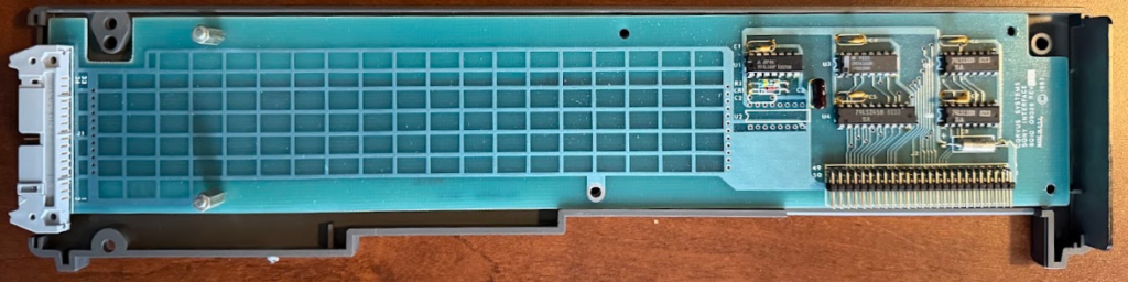
The drives came with a utility disk to modify the BIOS of CP/M versions 1.0, and 1.1, and to configure the hard drive, though it was never possible to boot from the hard drive as this module does not contain a boot ROM (if anyone has a copy of this utility disk, please reach out). Starting with Sony’s 1.2 release of CP/M it was possible to partition and format the drive directly within setup. Sony’s CP/M did not support partitions larger than 8MB (this was a CP/M 2.x limitation in general), so the 20MB drive needed to be divided into at least 3 partitions. According to the documentation, a drive could have a maximum of 7 partitions.
It appears that this module (and the drives) were only released in the US. Japanese users were offered another third-party option by BUG which had lower capacities (5 and 10MB).
SMD-70
After the release of the SMC-777 in Japan, there was a massive release of games, also in Japan. The SMC-777 was functionally similar to the SMC-70 in many ways, which meant that almost all of the software on the SMC-70 would run on the SMC-777, but the SMC-777 had a PSG (programmable sound generator) and two controller ports which the SMC-70 lacked.
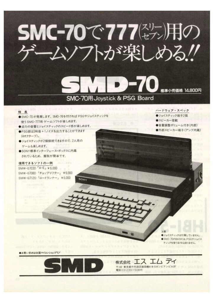
Since the opposite was not true, much of the SMC-777’s library will not run on the SMC-70, some users followed instructions in a magazine to create a so-called SMC-77 by putting the SMC-777 ROM in the open ROM socket, and running wires for a toggle switch outside of the computer to switch between ROMs. This was possible because while US SMC-70 systems had both ROM sockets occupied on the system board, in Japan, only one of the two sockets was used. While the SMC-777 had a higher color palette, the only other things that were missing were the controller ports and the PSG. A company named SMD created an I/O module that contained two RCA jacks for audio (line out and audio in), a built-in speaker, and two controller ports.
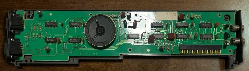
Since the SMC-777 was never released in the US, this module was never released in the US. Even in Japan it is relatively rare, as the SMC-70 wasn’t marketed as a home PC.
SMI-7016 – 8-inch FDD control unit
At launch, the 8″ floppy controller for the SMC-70 only supported single-sided, single-density 8″ floppy disks, though this was a software limitation. It was marketed that the SMI-7016 would be a general floppy disk controller, and would work with both 3.5″ and 8″ floppy drives, but this didn’t match reality. Sony themselves never sold an 8″ floppy drive, and the controller did not support Sony’s 3.5″ drives. The controller has a 37-pin female DB connector, but that connects to a 34-pin connector internally on the PCB, though at one point in marketing materials the connector was a 34-pin male IDC connector with locking tabs.
CCC (Computer Curriculum Corporation), which sold courseware to schools throughout the 70s and 80s, sold a branded version of the card. CCC also sold complete Sony systems with 8″ drives and CCC’s educational software. In Japan there is another variant of a floppy disk controller that uses a micro ribbon (aka Amphenol or Centronics) connector that has BUG branding on it, the company responsible for Sony’s Disk BASIC. It’s unclear if BUG created both versions, or created their own (if anyone has a picture of the insides of the BUG card, reach out!).
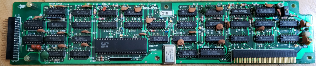
As time went on, Sony’s CP/M included support for additional 8″ formats (SSDD, DSDD), along with 40- and 80-track 5.25″ disks. It was possible to boot the computer from this controller card, but it wasn’t possible to swap between booting from an 8″ drive and a 3.5″ drive. According to Sony, if an 8″ drive is set as the system (boot) drive, a Sony 3.5″ drive cannot be physically installed in the system. If booting from a 3.5″ drive both drives can co-exist.
Sony’s CP/M supported drive letters A through P, but according to Sony, it did not support 16 physical drives. According to the CP/M Operating System manual, if using 3.5″ floppy drives, a 3.5″ drive must always be drive A, a maximum of four 3.5″ drives, four cache drives, and two 8″ drives can be installed, with no more than 8 drives total supported. The SMI-7016 disk controller supports a maximum of 4 drives. This may not be accurate though, it seems the real limitation is no more than 4 physical disks of any type, with a maximum of 16 total logical and physical drives (16 drives is the limit of CP/M 2.x).
SMI-7031 – RS-232C / SMI-7031A – RS-232C Programmable
The SMC-70 shipped with an internal serial port, and it was possible to add up to two more via these expansion cards. There were two versions of this module that were marketed, the SMI-7031 for $175 and the SMI-7031A for $300 (a difference of around $430 today). Opting for the programmable model meant a program like Softcom could adjust the baud rate of the card (110, 300, 600, 1,200, 2,400, 4,800, 9,600, or 19,200 baud), otherwise it had to be adjusted via switches internal to the card, which involved removing the module from the computer. The SMI-7031A is one of the devices that I have seen little evidence that it actually existed. Softcom’s manual references it, it is referenced in the April 1984 price list, and it is listed as existing in inventory (1 unit) in a 1990 audit of Chinese cable TV stations. If it did exist, the production numbers must have been very low. If it did exist, it’s odd that the service manual for the SMI-7031 does not mention the SMI-7031A.
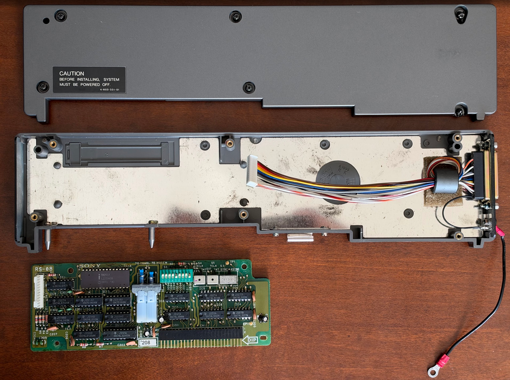
Both the onboard and the SMI-7031 RS-232C ports were controlled by an Intel 8251A USART chip. On the SMI-7031 there were two push switches for signal direction (pushing one caused the other to pop up, and vice-versa), a 9-switch block with 8 switches for setting the baud rate, and one for setting the card’s address. Three more individual switches control the receive and transmit clocks (internal or external) and set the card to synchronous or asynchronous mode.
The onboard RS-232 interface shows that the 110 baud setting is for 75 baud as well (set via a switch block); the internal port cannot be set to synchronous or asynchronous mode. The internal RS-232C port has a single switch for selecting the direction of the communication (to terminal, or to computer).
SMI-7032 – IEEE-488 / GPIB interface unit
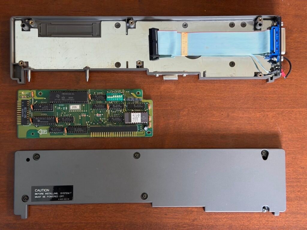
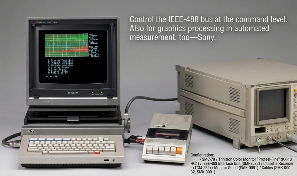
Looking at Sony’s marketing materials, it’s evident they intended the SMI-7032 to allow the SMC-70 to be used in scientific settings. The interface was originally called HP-IB, as it was invented by Hewlett Packard, so perhaps it’s ironic that HP was using the interface to connect Sony’s 3.5″ disk drives (via the 9121 expansion) to computers such as the HP 150. Aside from an IEEE-488 cable (SMK-0032; $94), Sony didn’t specifically market IEEE-488 accessories for the $300 card, but a few products they made contained the port, including oscilloscopes and waveform generators. The translated Japanese marketing photo below shows the SMC-70 controlling an Anritsu MS420B Network Spectrum Analyzer. BASIC and ROM BASIC did not have native support for the SMI-7032; support was extended by linking IEEE488.PAC (PAC standing for ROM pack) during program execution, which was included in ROM in the SMI-7032. An updated IEEE488.PAC file was included with every copy of Disk BASIC, and users were instructed not to use the version in ROM when using Disk BASIC.
GPIB ports were options on most 80s PCs, from the Apple Macintosh and Commodore 64 to the IBM PC and compatibles, but were always fairly rare. Even today it’s possible to get a USB to GPIB adapter for around $60 to support existing equipment. In a way, the standard reminds me of Firewire and USB 1.1. Compared to serial, GPIB offered much faster speeds, up to 1 MB/s, and (depending on the platform) users could connect up to 31 logical devices. Being a parallel bus, more wires are used to transmit data compared to serial, though in the US Sony charged the same price for their RS-232C cable, despite it only having 13 conductors, while GPIB has 24.
SMI-7050 – 256K RAM Cache Disk Unit
Though the SMC-70’s floppy drives have twice the transfer rate of typical floppy drives, they are still a bottleneck when it comes to accessing data. Sony’s solution to this was a 256KB RAM disk, a drive with a capacity 24KB smaller than a floppy disk. Depending on the marketing material, Sony claimed the drive improved compiling times by 300-500% and provided a 70x improvement over random access times compared to using the floppy drive.
The drive was presented to CP/M like an actual floppy drive, with 64 tracks, 32 sectors per track, and 128 bytes per sector. It had a data transfer rate of approximately 672 microseconds/sector, which is approximately 190KB/second. Of course, the system bus will not allow for sustained data transfers at that speed.
The SMC-70 supports 4 cache disk units, and though the service manual states that 16 can be added, this would be physically impossible to do. Release 1.0 of CP/M 2.2 will allow 5 units to be added under setup, but it’s not possible to save data to the 5th drive. Release 1.1 will also allow 5 units to be added, but the system will not fully boot with the 5th installed. Beginning with release 1.2 it wasn’t possible to configure more than 4 drives in setup.
Next to the floppy drive unit, cache drives are perhaps the most common accessory for the system. At a price of $875 they weren’t exactly cheap (~$3,025 today). In fact, when the SMC-70 launched they were the most expensive module Sony released (the superimposers would later take this crown, then the Videotizer), but they made accessing data orders of magnitude faster. In 1984 it was possible to get a system with CP/M for the same price as this module. Early models contained 32 Mitsubishi M5K4164NS (65,536 bit, 150ns) dynamic RAM modules, while later models used 32 Fujitsu MB8264A (65,536 bit, 120ns) dynamic RAM modules, for a total of 256KB of usable space. There was a red LED on the right side of the module to indicate when the disk was active.
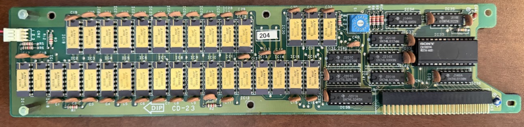
CP/M needed to assign a drive letter to each module, which was done in the setup utility. If there was only one module installed, nothing else was required by the user. If more than one module was installed, the user also had to select one of 16 addresses via a rotary switch under an access panel, beginning with 0 (0-9, A-F). The lowest numbered drive would be the first cache drive assigned a drive letter (the actual number/letter selected didn’t matter). The system will not recognize if more than one drive is assigned the same address, CP/M will just read and write to all of the drives with the same address as if it’s a mirrored array.
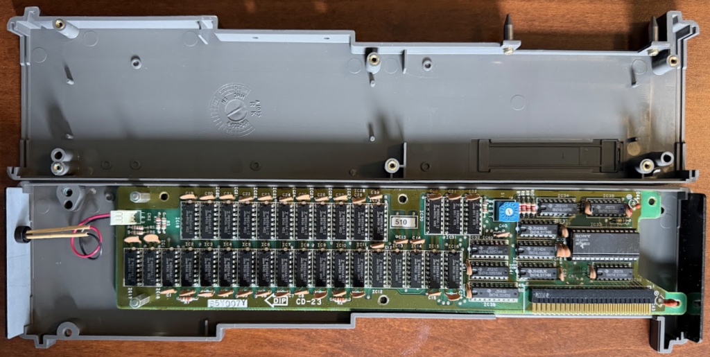
There were many uses for the cache disk, the first being in the name, to use it to cache data, though it was only able to store program data, a program could not be executed from the cache. This could only be done directly through assembly programming, and code samples were provided in the user manual. This would have been a useful feature if companies released software that took advantage of the drive being installed in the system, but this did not come to pass.
But the main purpose was as a RAM disk. This was all but a requirement for anyone using the SMC-70 or SMC-70G to do real-time tasks when using programs like Video Titler or Q-Manager; the user manuals for both programs have instructions for using the cache disk. Many users took advantage of a feature of Sony’s CP/M to automatically execute a file at startup (along the lines of a rudimentary autoexec.bat), which in later versions of Sony’s CP/M had the character limit expanded to increase the functionality of this feature so that a user could chain commands. This allowed a user to create a submit file that contained a command to copy all of the files from the floppy disk to the cache disk, and then start the relevant program. After the user was done working, they would close the program, and then all of the files would be copied from the cache disk back to the floppy disk and the user would turn off the computer. While the data in the cache disk will survive a system reboot, it will be lost in the event of a power failure, which was one of the reasons users might be tempted to install the battery backup module (SMI-7080; $350).
SMI-7051 – 192K Bank RAM Unit
Almost nothing is known about the bank RAM add-on; it’s quite likely it was never released. The card was not available when the system was released in 1982 and was estimated to be released in Q1 of 1983. It was not on US price lists as of April 1984. It was mentioned in a January 1983 article about the system’s launch in Japan in Monthly Microcomputer (Micom) and listed as “coming soon” in Japanese marketing materials through March 1983. In the April 1983 brochure, it was removed. It was never pictured in any marketing materials.
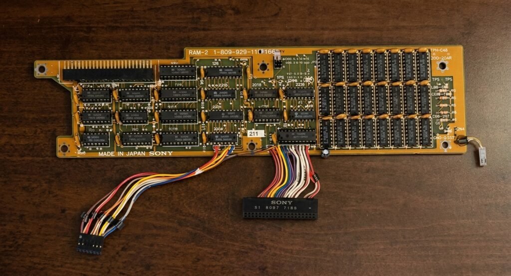
There is one known photograph of it from the Sony Hardware Manual, which was a small binder given to dealers that listed all of the parts available for the system. Based on the fact that this manual lists the A variant floppy drives (auto shutter), it likely was published on or after April 1983.
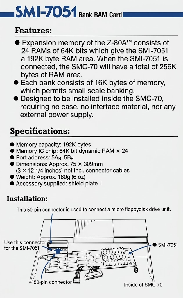
The card connects to an internal expansion connector, which would limit where it could be installed. Japanese systems had 1 of the 2 internal expansion slots used by the ROM board, while the second expansion slot was almost always used by the floppy drive controller. This effectively eliminated the entire Japanese market as potential users. When it comes to the SMC-70G, it has 3 internal expansion slots, but the available slot will not mount a full-length card, eliminating any SMC-70G as a potential candidate for the card. It’s not difficult to see why the bank RAM card was canceled, especially when the Cache Disk Unit (SMI-7050) could likely fulfill a similar purpose for users.
The card came with 4 connectors. The 50-pin connector on the rear connected to the system bus. It’s a guess what the other 3 connectors were used for, if they were used at all. The first connector was a 14-pin, next was a 40-pin, and to the right was what looks like either a 2- or 4-pin connector. While there was a 40-pin diagnostic port for the Z80 processor that the 40-pin connector could have plugged into, there were not open 14- and 2/4-pin headers on the motherboard. Without a user manual, it’s unknown what the function of these wires was.
Perhaps at some point Sony was considering offering CP/M 3.0 as an OS, and thought being able to add more RAM to the system would appeal to some users. At any rate, it appears to be one of the few announced, but never released, products for the SMC-70.
SMI-7052 – Kanji ROM Kit
Speaking of things that may never have existed, this is the first accessory on the list that wasn’t marketed (or available) in the US, though it may not have been available anywhere! It was to be released in the second quarter of 1983. The Kanji ROM Kit was created to add Japanese kanji characters to the system, as there is not enough space in ROM to store them there. The system ROM was already expanded for the additional Japanese (and other) characters that were added when the system was released in Japan a few months after the US launch. While US systems shipped with 2 16KB ROM chips, Japanese systems shipped with 3. The kit was advertised as containing 3,000 level 1 kanji characters. My guess is they decided to rename this part, since it didn’t fit in the naming scheme (it wasn’t an external expansion module), and it was released as the SMK-0052.
SMI-7054 – Kanji ROM unit
Unlike the previous ROM kit, this module did exist and was released in conjunction with the SMC-70G. It offered 3,755 JIS level 1, 3,008 JIS level 2, and 682 foreign high resolution 24×24 dot characters, including English, Greek, Japanese, and Russian, along with Arabic numerals. This was an upgrade over the 16×16 dot level 1 characters provided by the optional SMK-0052 ROM kit. At ¥180,000 it was an expensive add-on, but that price was likely in part because it contained 18 32KB ROM chips, giving 576KB storage.
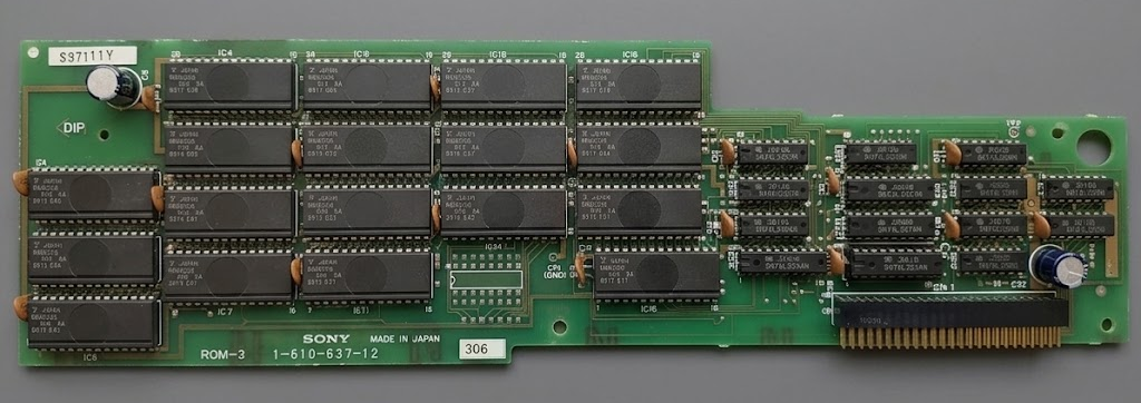
The module was intended to be used in conjunction with the Japanese edition of Video Titler (also called Japanese Video Typewriter, SMW-7074, ¥70,000). The program was used to superimpose text on top of video and could be used in broadcasting, training videos, and sales presentations.
SMI-7055 – Chinese Character ROM Module
The Chinese Character ROM Module was released with the SMC-70GP in China and included even more storage than the SMI-7054. It contained 7,445 characters (3,755 level 1 and 3,008 level 2 Chinese national standard characters and 682 foreign characters including English, Greek, Japanese, and Russian, plus Arabic numerals) in both 16×16 dot, which took up 250KB of space, and 24×24 dot, which were took up 562.5KB of space, for a total of 812.5KB of data.
This was a massive amount of data to store in ROM, as ROM prices did not begin to ease until the 1985 price collapse due to oversupply. Since SMC-70GP models only contained a single 16KB ROM chip, they likely did not ship with the ROM subboard that other Asian market SMC-70 machines did, which meant it was not possible to install the SMK-0052 Kanji ROM Kit containing any of the Japanese characters.
Chinese characters can be entered by typing a 4-digit numeric code (there was not a Chinese keyboard layout). The 3,755 level 1 characters can also be retrieved using Chinese Pinyin phonetic rules. The module was designed to be used with the Chinese Video Titler software (SMW-7077). Both were jointly developed by the Beijing Institute of Posts and Telecommunications (now the Beijing University of Posts and Telecommunications) and Sony. It’s difficult to pin down the exact release date of the SMC-70GP in China, and the release of this module.
SMI-7056 – 256K Supercharger RAM
This is the first accessory that isn’t for the SMC-70, but rather for the 16-bit Intel 8086 Supercharger add-on, the SMC-7086. The Supercharger came with 256KB of RAM in the form of the SMI-7056 ($625) RAM card and had two additional slots to add 512KB of additional RAM. There was one magazine that reported that the Supercharger would be able to be configured with 1MB of RAM, so it’s possible at one point that Sony was either planning on allowing 4 of these boards to be added to the Supercharger, they planned on installing RAM on the system board of the Supercharger itself, or the reporter just heard wrong, though the user manual for the Supercharger shows that up to 1MB of RAM can be added/supported. But when the device was released, the maximum RAM supported was 786KB, and two additional cards could be added. The pricing was interesting, as the Supercharger itself retailed for $895, and included a RAM card, which means without the RAM card the device itself was being valued at $270!
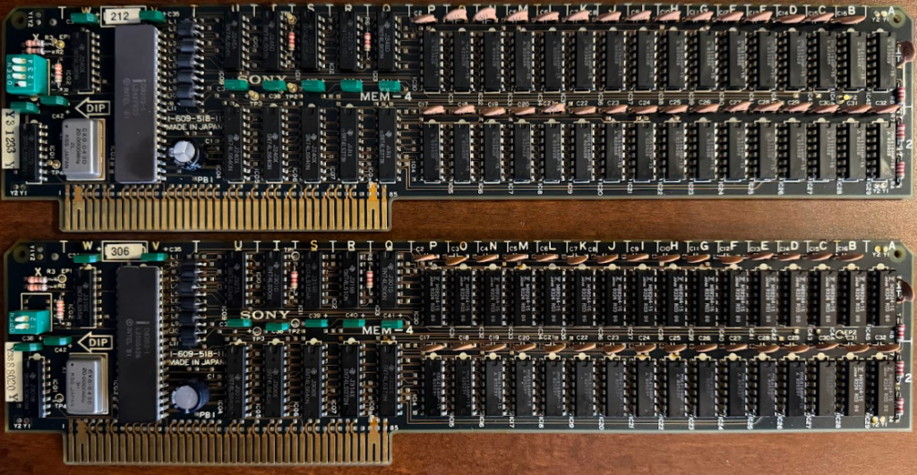
There are two versions of the board, one with a 4-switch switch block, and one with a 2-switch switch block. The switches are used to set the card ID. Sony used both Fujitsu MB6284-15 and Mitsubishi M5K4164NP-15 64Kb DRAM modules, sometimes on the same card. This is similar to the RAM used in the cache disks.
SMI-7073 – RGB Superimposer
The RGB Superimposer (SMI-7073) was one of two superimposers released by Sony. Although both were compatible with the SMC-70, they were introduced with the release of the SMC-70G. Sony announced the SMC-70G and NTSC Superimposer (SMI-7074) on September 29, 1983, though both (and the SMI-7073) were listed in an announcement in the August 1983 issue of IEEE Computer Graphics and Applications. Examples of the SMC-70 superimposing text on video existed well before Sony announced any superimposers; as early as January 1983.
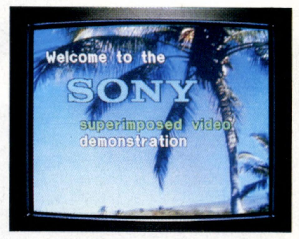
I’m sure prospective buyers seeing this ad in magazines weren’t at all deceived about the abilities of the SMC-70! In the June 1983 issue of the same magazine (Monthly Microcomputer), in a review of the Sharp X1 (which could superimpose), the authors pointed out that sometimes people misunderstand and think that the SMC-70 can also superimpose, but the computer cannot combine the computer display with the video disc (LaserDisc) that Sony is scheduled to release (obviously the authors had no idea what Sony had in the works). The Sharp X1 superimposer was more like Sony’s RGB Superimposer in that output couldn’t be recorded or combined with television broadcasts or VTR images.
Sony was tight lipped about pricing for this equipment compared to the standard SMC-70 equipment, perhaps because they planned on negotiating based on the package ordered or volume. There are no published prices in the US for either superimposer.
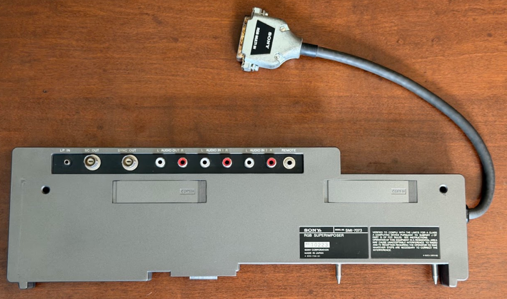
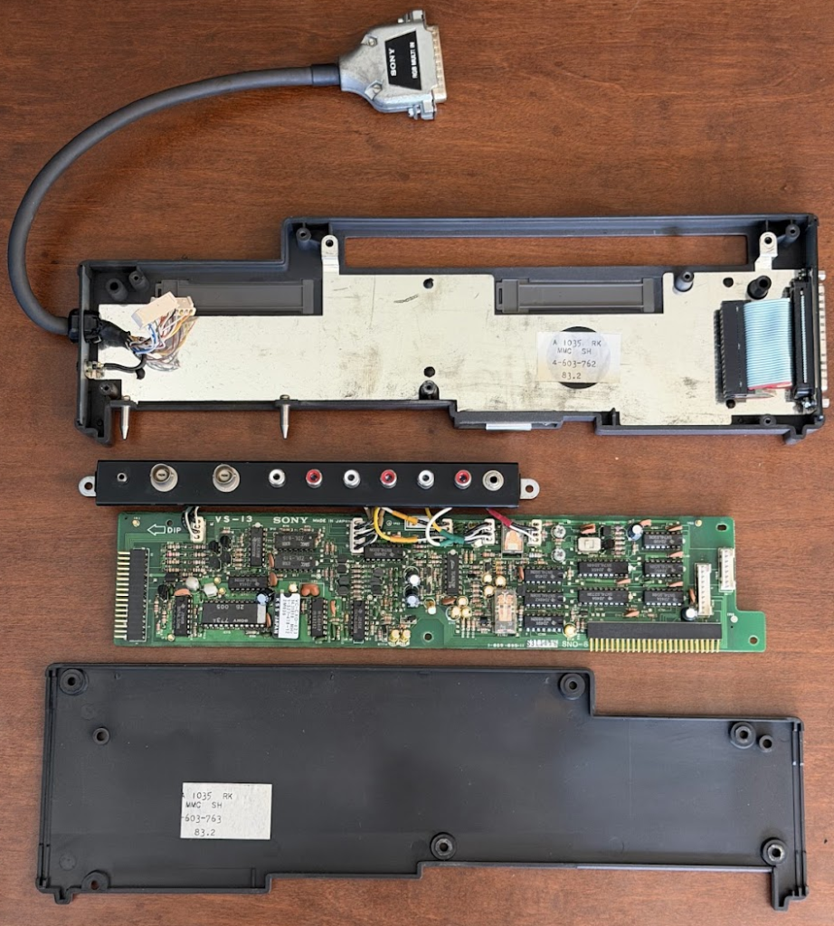
The RGB Superimposer occupies a single slot, though it is taller than a typical module in order to accommodate the external connectors. On the left side of the module is a 25-pin RGB-in connector that connects to the video-out port on the computer. On the right side of the module is a 37-pin connector that will connect to the monitor. They sold two cables that connect to this port, the SMK-0073KX and the SMK-00073PV. As you might guess from the part numbers, the first cable connects to KX series monitors, and the second cable connects to PVM series monitors. Why Sony went with a 37-pin connector is a mystery. There doesn’t seem to be any reason why Sony couldn’t have just used the same 25-pin connector that was on the computer, which would have allowed users to reuse their existing monitor cables. Inside the module only 34 wires are connected to the 37-pin connector, many of them ground wires.
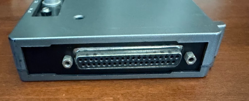
On the back of the module are 10 connectors. The first is LP in, which connects the lock pulse signal from an LDP-1000/LDP-1000A LaserDisc player. Next is SC Out, which is a chroma subcarrier signal synchronized with the analog RGB signal from the SMC-70/70G. The second BNC connector is Sync Out, which is a composite sync signal synchronized with the analog RGB signal from the SMC-70/70G. Then there are 3 sets of RCA jacks. The first set is for Audio Out. Audio can be selected (from software) from the next two sets of jacks, the Audio In 1 or Audio In 2 connectors. Finally, the last jack is Remote, which can connect to the remote jack of an audio cassette deck to start or stop the unit via software. This is similar to how the cassette deck port can control a cassette recorder. The cassette deck port can also be used with the module when using Q-Manager, as it can carry a cue tone to the video device.
The primary difference between the RGB Superimposer and the NTSC Superimposer is that the NTSC Superimposer was meant for content that was going to be recorded or broadcasted, while the RGB Superimposer was meant for content to be viewed in real-time. Examples include using a light pen to draw on top of a video the way a weatherman or sports commentator does, for business presentations, and for marketing purposes (videos could play in stores, and text about products or prices could be super imposed). There was also an entertainment aspect. At the time, people thought video was going to be the next big thing in computers. Even before the release of the SMC-70 Sony was hyping how the system would interface with videodisc players and recorders(!) once available in the coming years. Once the superimposer was released there was a possibility for creating full-motion games, though this didn’t come to pass. It’s funny to imagine that a game like exceptionally highly rated Marky Mark and the Funky Bunch: Make My Video for the Sega CD released in 1992 would have been higher quality if released 9 years earlier on LaserDisc for the SMC-70 with the Supercharger (I’m not saying that would have made it any better of a game). Many FMV games would have been possible. The July 1984 issue of Byte magazine provided a sample program to create this type of choose your own adventure game.
There was an art piece that used just this concept, Roberta Friedman and Grahame Weinbren’s The Erl King, which ran on an SMC-70 with an RS-232C module (SMI-7031), 256K RAM cache disk (SMI-7050), an RGB superimposer (SMI-7073), 3 Sony LDP-2000 Laserdisc players, and a Carroll touchscreen, all of which is now stored in the Guggenheim. A document about the configuration said it had “two control ports” that were originally designed to control audio cassette tape players that served as file storage devices, but this does not make much sense as the SMC-70 has a single cassette deck port, plus the author said these ports controlled a custom-built “video switcher” that could switch the outputs of any of the three LDPs to the display. It’s possible the audio-out and remote control lines were both used as separate signals in the cassette-out connector to control the video switcher, though in numerous places the author refers to the computer having two audio cassette ports. It’s also possible the second port the author was referring to was the remote control port on the RGB superimposer, or the light pen port (Q-Manager used both both the cassette port and light pen port to interface with a video editing controller, and to a user, the ports look similar). The text and images to be super imposed were stored on floppy disks (this makes much more sense than what was mentioned about storing data on cassettes). The serial ports were used to control the video and audio outputs of the LDPs and to get input from the touchscreen.
Because the RGB Superimposer output couldn’t be recorded (a limitation that doesn’t exist today), it didn’t wind up having as many practical commercial uses and thus isn’t as common as the NTSC and PAL superimposers.
SMI-7074 – NTSC Superimposer / SMI-7074P – PAL Superimposer
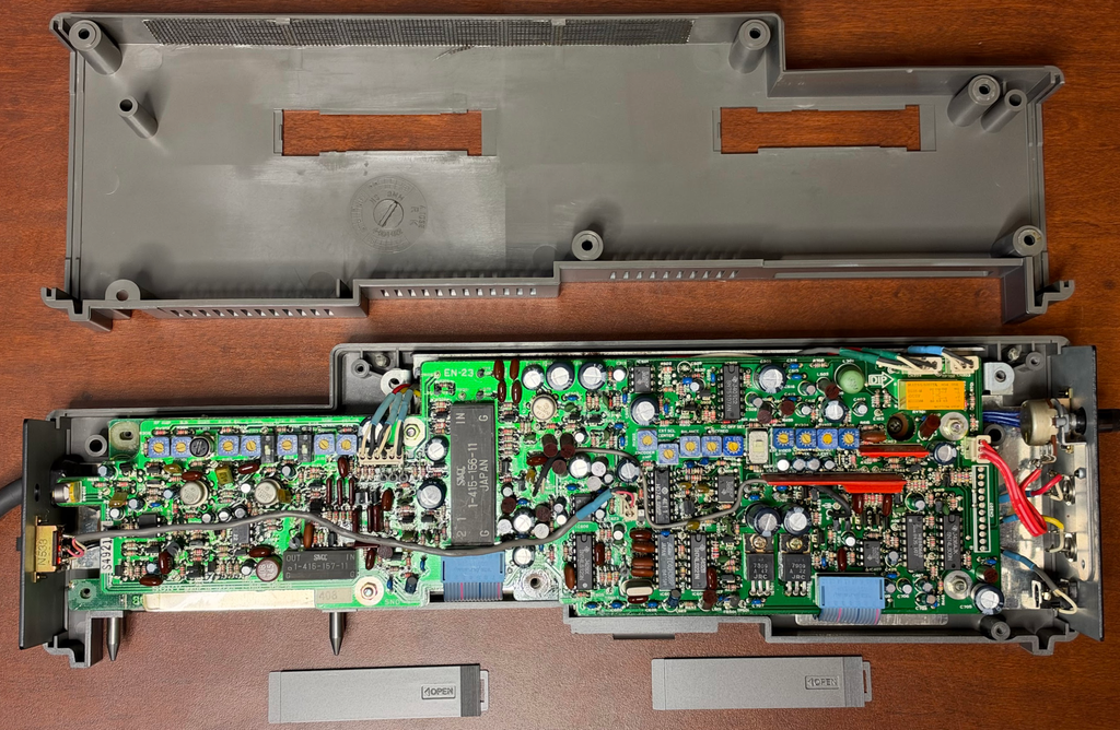
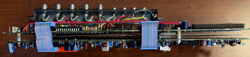
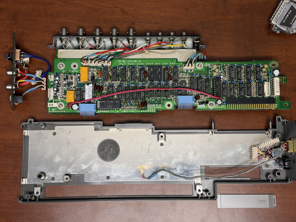
The NTSC and PAL superimposers allow the output to be recorded, and the electronics to make this possible resulted in substantially larger modules; Sony’s only dual slot modules (though only one connector is used on the 50-pin bus). The modules are identical other than one supports NTSC while the other supports the PAL format. While I haven’t been able to locate US pricing, in Japan the unit sold for ¥230,000, or around $1,500, which was slightly more than the price of the base SMC-70 at launch. This modules is the most common accessory with the SMC-70G/GP.
Like the RGB Superimposer, these modules are taller than regular modules, allowing various cables to be connected. On the left was a video-in cable that connected to the video-out port on the computer. On the right-hand side is a switch to select color or black and white output. Next to that is a knob to adjust the chroma level when output is set to color. Under those is set of RCA jacks for Audio In 2; Sony suggests connecting to a cassette deck to these jacks, and under those is a remote control jack to control the cassette deck (play/pause).
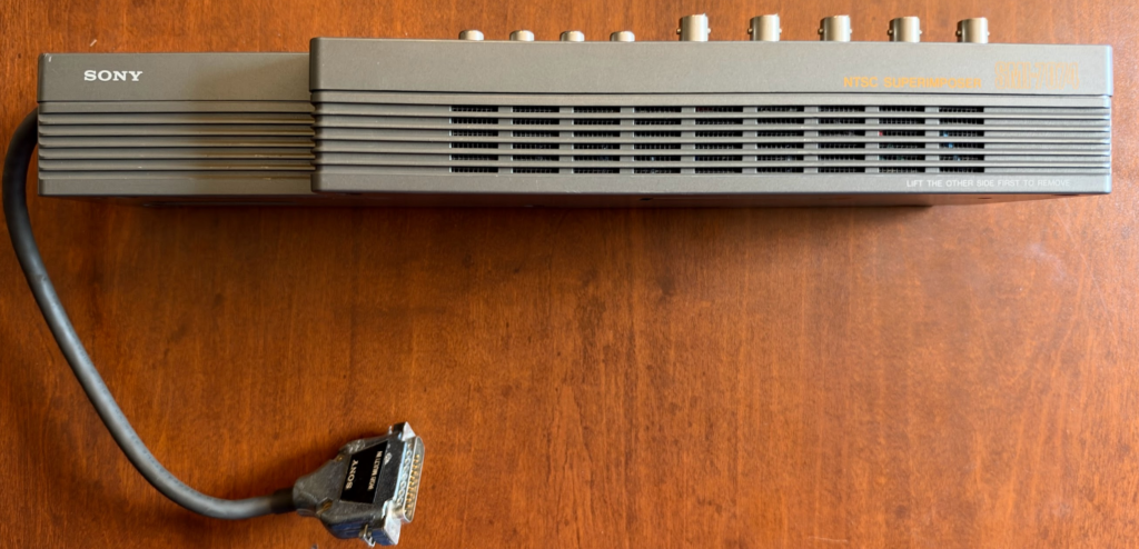
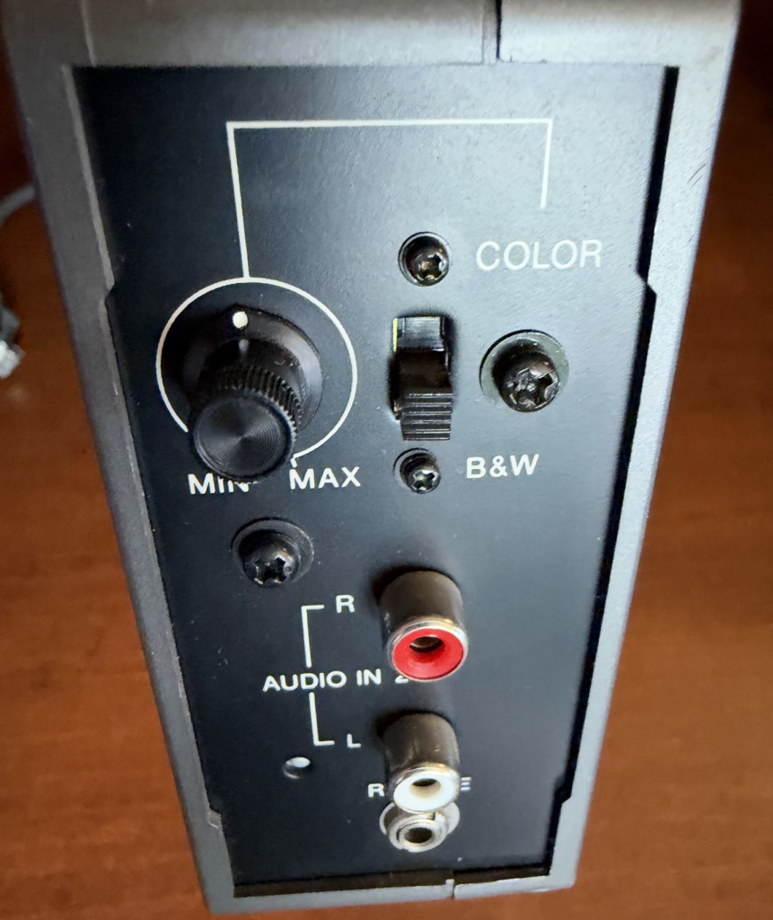
Facing the back of the module, from left to right on the top is the video in BNC connector and 2 video out BNC connectors. These two connectors output the same signal, though when the computer is powered off, video will pass through the first connector, but not the second. Next is a Sync Out BNC connector, which is a composite sync signal synchronized with the analog RGB signal from the SMC-70/70G. To the right of that is another BNC connector, SC Out, which is a chroma subcarrier signal synchronized with the analog RGB signal from the SMC-70/70G. Then there are 2 sets of RCA jacks. The first set is for Audio In 1, and the second is Audio Out. Audio can be selected (from software) either the Audio In 1 or Audio In 2 inputs. The final input is LP in, which connects the lock pulse signal from an LDP-1000/LDP-1000A LaserDisc player.
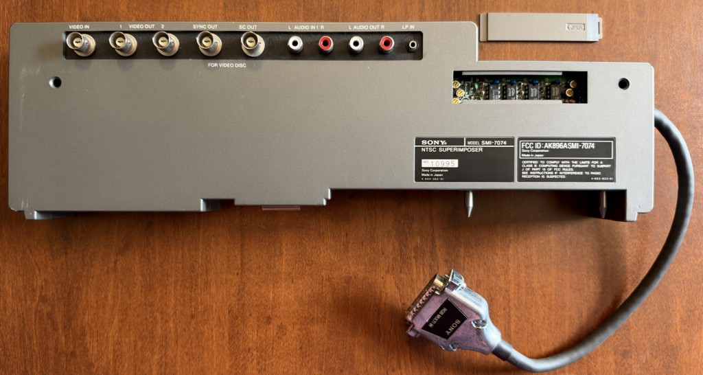
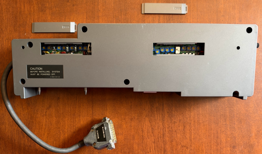
While the module can be used with either the SMC-70 or SMC-70G, if it’s used with the SMC-70, unlike the RGB Superimposer, it’s not possible to use it with a KX series monitor as the video output is through 2 BNC connectors, which the KX series monitors do not have. This meant SMC-70 owners had to potentially upgrade their monitors. When the SMC-70G was released, Sony introduced a line of monitors for it, the PVM series. In reality, most users who were using an NTSC/PAL superimposer with an SMC-70 were likely doing so in a broadcast environment with plenty of A/V equipment around to capture and display the signal and weren’t using the system for general business tasks like word processing.
SMI-7080 – Battery backup
The battery backup isn’t an RTC battery backup (that’s internal to the system), but rather a mini uninterruptible power supply. The key word here is mini. Speculation is that this module was created out of necessity for Sony (or BUG), and not just with consumers in mind. The battery wasn’t cheap, $350 in 1983 money (~$1,175 in 2026), so the data it was protecting really needed to be valuable.
The battery setup was odd though. Internally, it contained a nickel cadmium battery pack that provided up to 42 seconds of backup time (when new). It needed to be replaced every 2 years. But it wasn’t capable of providing an uninterrupted 42 seconds of power; there was a transistor-based timer circuit that would provide approximately 7 seconds of power before the battery would cut off, killing power to the system. This meant that the battery module was really more useful in a power blip than an actual power outage. It could protect against six 7-second outages before the battery was exhausted.
It wasn’t exactly a performer when it came to charging either. Every 4 hours of charging time restored 2 seconds of protection, which meant it only took 84 hours, or 3.5 days to fully charge the battery. We’re not talking about a car battery here, this was a Ni-Cad battery pack that fit into a standard Sony expansion module! It just charged at 20mA (at 12v), which is 0.24 watts; it shows how careful Sony was to avoid overloading the power supply. It could output a maximum of 45.4 watts. The battery could only charge when the system was powered on.
While the module fit into one of the expansion slots, it did not plug into the 50-pin bus. Instead, there was a 5-pin power connector that ran from the battery, along the 50-pin bus connector, into the system, where there was a second 5-pin power connector that’s identical to the one used by the power supply. Because of this, the module needs to be installed in the first slot in the system.
To use the module, first the system is turned on, then a power switch on the right side of the module is turned on. To shut down the system, the module is powered off, and then the system. There are three LEDs above the power switch, a warning indicator, ready indicator, and in use indicator. The warning indicator will flash and a beep tone sound intermittently if the system is turned on but the battery backup remains switched off. During a power failure, the in use and ready indicators will illuminate. If the power loss is less than 0.5 seconds, the in use indicator will turn off. If not, a beep tone will sound continuously. After about 5 seconds the system will likely lose power. Sony suggests using the computer at least 4 hours a day (20 hours a week) to maintain a full charge.
The reason for the battery only providing 5- to 10- seconds of backup is described in the manual as a mechanism to protect the battery from over discharge; there isn’t an actual timer, but simply voltages that are being monitored. If the +12v rail drops below 8.3 volts, +5v drops below 4.5 volts, or -12v is lost, all power is cut. If the battery pack were rebuilt with a more modern chemistry, the module could be a bit more useful. The battery pack itself appears to have been comprised of 14 1.2v 600mAh cells wired as two 7-cell battery packs in a single pack, likely making the pack 8.4v @ 1,200mAh, but the system combines the two packs (8.4v + 8.4v) to create 16.8v @ 600mAh (this is one module I don’t own, so I cannot verify this).
External Expansion Options
SMI-7040 – Expansion Unit
As previously mentioned, the SMC-70 had 3 external expansion slots, while the SMC-70G had 4. A user could quickly run out of space to expand the system (in practice, this wasn’t really an issue, making the expansion unit quite rare). There were two solutions to this; one from Sony was a 5 module expansion unit that sold for $575, the other was an 8 module expansion from BUG that was only available in Japan (the BUG option required modules to be removed from their cases). Because it had its own 50-watt power supply, users didn’t have to worry about overloading the main unit. Because the power supplies are isolated, the battery backup (SMI-7080) module can’t power the SMC-70 when installed in the expansion unit. Theoretically it should be possible for a second battery backup to power the expansion unit if the power connectors were spliced together, obviously not something suggested at the time. This is something for a user to be aware of if installing a cache disk unit (SMI-7050) in the expansion unit and a battery backup in the main system; in the event of a power failure, the data in the cache disk would be lost.
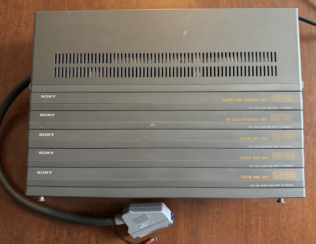
The expansion unit is fully buffered, which means there is added latency when transferring data to and from modules installed in the unit compared to modules installed directly in the system, though in practice the impact is negligible. For example, transferring 256KB of data between 2 cache disks installed internally averaged 17.8 seconds, 2 cache disks externally, 17.8 seconds, and 18.2 seconds with 1 cache disk installed internally and 1 externally.
The process of adding and removing modules to the expansion unit is similar to the main computer. Two screws on the side are slightly loosened, the guide pins are removed, and the front can be extended to accept 1 to 5 modules. The modules fit back to front, instead of front to back. After a module is inserted, the pins are replaced and the screws are tightened.
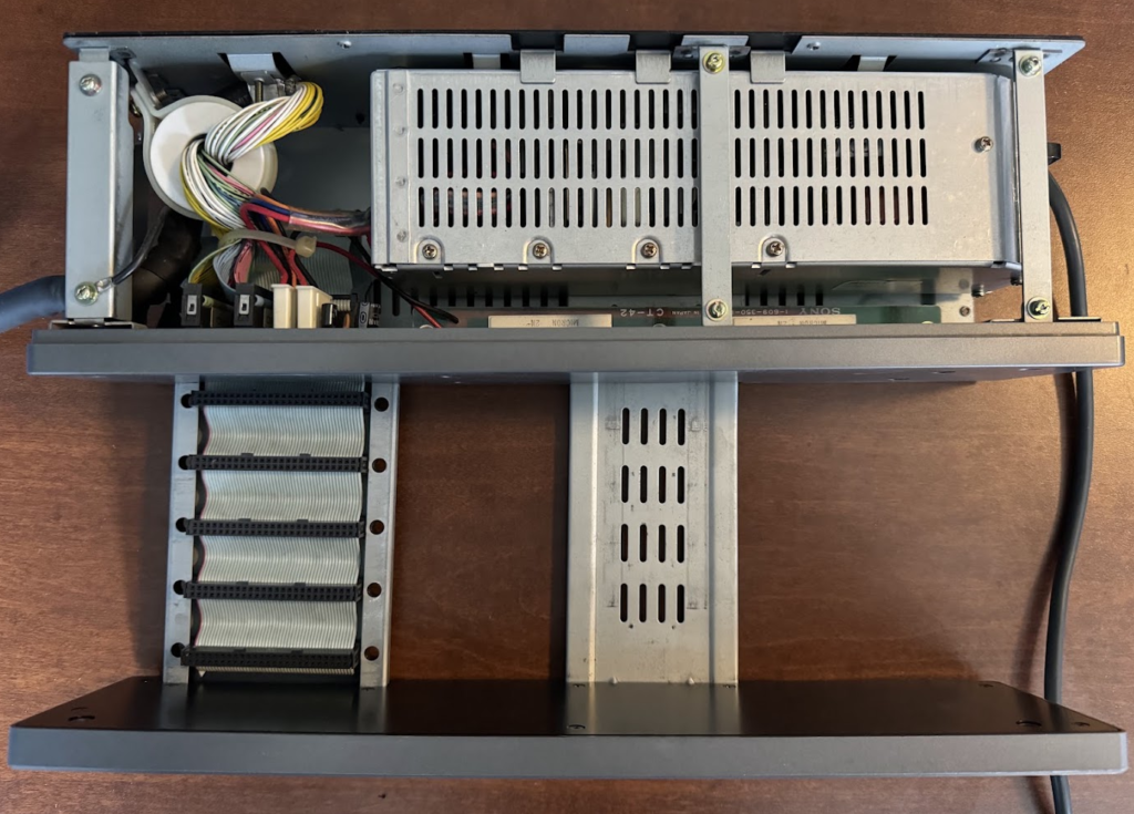
One downside to the expansion unit is it’s not possible to daisy chain the Videotizer (SMI-7075/P) or Supercharger (SMC-7086) off of it, so users have to decide which of the three external options they wish to use. I am somewhat surprised Sony didn’t release a 2-in-1 or 3-in-1 adapter to connect to the back of the SMC-70 or add a pass-through connector to each expansion unit.
SMI-7075 – Videotizer (NTSC) / SMI-7075P – PAL Videotizer
The Videotizer is a dedicated piece of hardware that allows users to capture still images from a composite video source and either perform special effects on the image and forward them on or download an image to the system. Saved images could then be edited in Graphics Editor or displayed in any program capable of opening Graphics Editor files, such as Disk BASIC.
The accessory was the third and final external expansion Sony released for the SMC-70 and considering the pace of technological advancement in the 80s, it was released relatively late in the system’s life, with a scheduled release of November 21, 1984, about a year after the release of the SMC-70G, though it appears it actually launched in early 1985. The Videotizer plugs into the 50-pin expansion port in the back of the unit and is intended to sit directly on top of the system using parts that were also included with the monitor stands (the SMK-0091A or SMK-0091B with the SMC-70 or the SMK-0091B with the SMC-70G). With the Videotizer connected it’s not possible to connect the Supercharger or 5-module expansion unit, as they all require the same 50-pin expansion port.
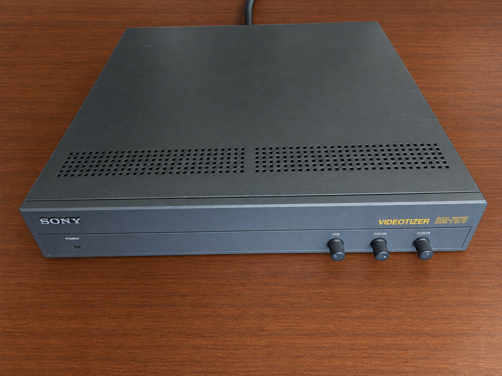
Similar to other expansion options, the Videotizer works with both the SMC-70 and the SMC-70G. The Videotizer has to work around a key limitation of the SMC-70; the computer only supports 16 colors. To get around this limitation, the Videotizer has its own 256KB of RAM, which makes it capable of capturing images at 448×242 in 256 colors (108,416 pixels) (though the announcement in Japan says the resolution was 448×262, while an announcement for the Chinese market SMC-70GP PAL version says it captures 448×292 pixels, while a French article says the PAL version’s resolution is 448×287…did anyone know!?), and only when images were downloaded from the Videotizer’s frame memory to the SMC-70’s memory would images be converted to 320×200 at 16 colors. The discrepancy might be related to the NTSC and PAL hardware differences. The NTSC software specifies a window of 448×241, while the PAL software specifies 448×291.
The capture resolution is an interesting choice, as it’s a widescreen ratio (~1.85:1) that was regularly used in theatrical releases. This meant it was possible to choose which part of an image was captured and saved to the system. If the unit is connected to the Sony SMC-777 with the optional color palette board or the SMC-777C, images are saved with 16 colors but with colors selected from the expanded palette of 4,096 colors.
The unit can also slice a video, storing up to 16 frames of a video in memory. Images can also be uploaded from the SMC-70 to the Videotizer so the unit can perform effects on them. The unit comes with its own software with separate NTSC and PAL versions.
On the left of the Videotizer are two DB25 ports, one for RGB in, and another for RGB out. Unlike the superimposers that had built-in cables, the Videotizer did not come with a built-in cable, though a 1-meter 25-pin video cable was included. The cable theoretically would make it possible to locate the unit further away from the computer, but the built-in 50-pin connector to connect the Videotizer to the computer is at a right angle (and faces awkwardly away from the computer), and the cable is roughly a foot long, making the top of the system the logical place to install it, though it can also go to the left of the system. Part of the reason why the video cable might not have been hardwired could have been because it was not a requirement to actually connect the system’s video-out to the unit when using the Videotizer as a capture device, nor did the device need to be connected to a monitor. It was only necessary to connect these cables when using the Videotizer in conjunction with a superimposer.
Looking at the rear of the device, on the left was a power switch and a detachable AC power cord with a separate grounding lug. While US SMC-70 power supplies are 120v/60Hz and Japanese systems are 100v/50Hz, the power supply in the Videotizer is universal and does not differ between countries, even though it is listed as 120v/60Hz/50Hz (and not 100v).
Next there are 2 BNC composite-in jacks with 75Ω switch and a position offset switch, the 50-pin external cable, 6 BNC ports (R, G, B, and Sync on top, Key (with delay switch) and B&W on the bottom), and a small (somewhat noisy) fan. I replaced this on my unit. The front of the unit has 3 control knobs on the right-hand side for hue, color, and contrast.
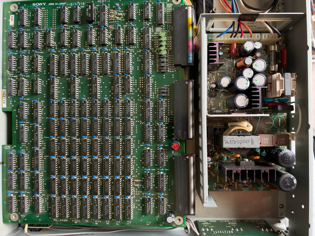
Internally, the right third of the unit contains the power supply, while the left two-thirds has two stacked PCBs. The bottom board contains the video processing hardware and video I/O, while the top board holds the 256KB of RAM and handles system I/O. Somewhat surprisingly, Sony used the same rails for the left and right sides of the unit, which means there are also 2 cut outs on the right side for the RGB cables on the frame rails where the power supply is.
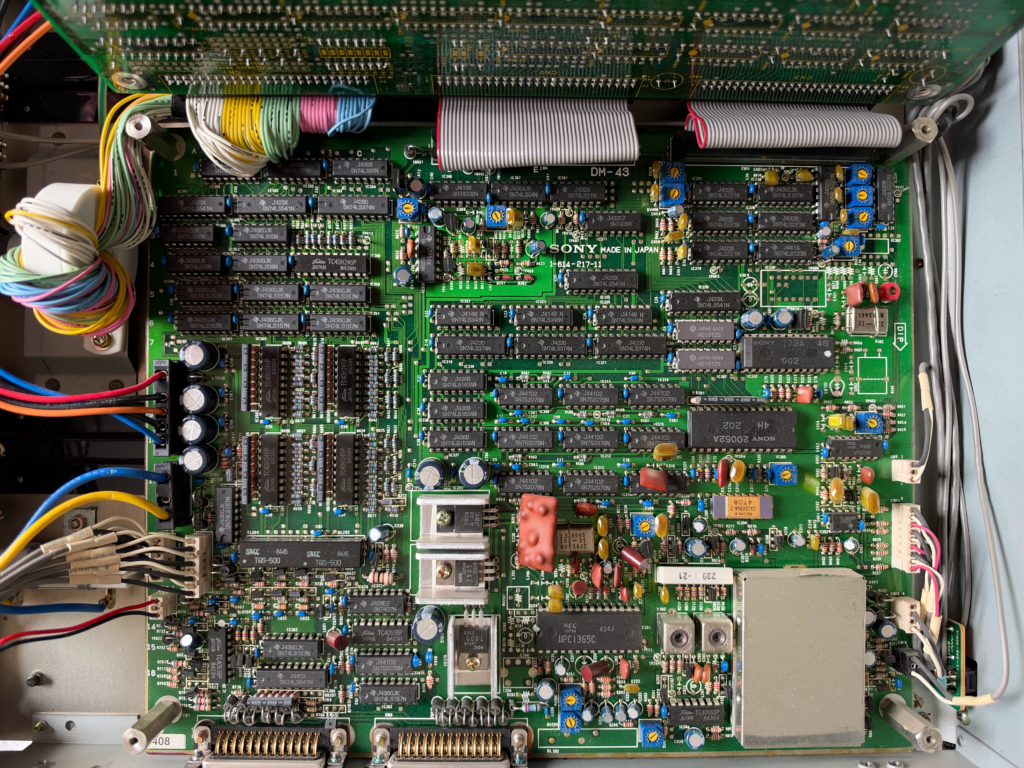
As you might imagine, the functionality offered by the Videotizer did not come cheap! At a price of $3,105 ($10,010 in 2026), the Videotizer was the most expensive item Sony released for the SMC-70. By this point it’s safe to say Sony knew the SMC-70 was a commercial failure, but the system had a place in their broadcast equipment lineup. It’s perhaps for this reason that so many people think the system wasn’t a general business machine, but was made for broadcasting. The system just had an exceptionally long life in the TV industry, seeing use into the 90s.
As mentioned, there were two uses for the Videotizer. The first was to import graphics into the SMC-70 without having to draw them by hand. It could import images in color, greyscale, and black and white. When capturing images, the user could use the black and white mode to capture the outline of an object that could then be further modified with Graphics Editor. It was possible to make monochrome images of any of the 16 available colors, not just black and white. With the unit, TV stations could create their own graphics faster and with less effort than if they drew them by hand, which saved labor and the cost of having to buy graphics from an outside company.
The second use was to generate special effects in conjunction with either a NTSC or PAL Superimposer. While Q-Manager offered the ability to do various wipes with the Superimposer, the Videotizer offered additional effects. When used this way, Sony advertised the ability to zoom in 30x on pixels to generate a mosaic effect. The 16 still images the device can store can be cycled through like an animation. But the easiest way to explain what the Videotizer could do is to see it in action! Sony created this ~9 minute gem of a marketing video to demonstrate the unit’s capabilities. They used images from the video in other marketing materials. You can see all of the special effects the Videotizer is capable of in this video.
A dedicated monitor can be connected to the Videotizer, allowing users to see a live image from the connected source or the captured image in the Videotizer’s frame memory. This would be the third monitor connected to a system with a superimposer! Though this third monitor is not required, when using Quick Titler (SMW-7078), the Videotizer can be used as a staging monitor for previewing and selecting the image to superimpose next. The main monitor would be displaying the current image being superimposed, while the monitor connected to the superimposer would be displaying the combined video and graphic for broadcasting or recording.
The SMI-7080 is the last part number in the SMI list, though the SMI-7075 was the last device released.
Accessories
SMK-0001 – Monitor Cable
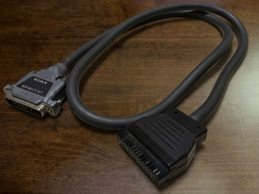
The SMK-0001 is the monitor cable used to connect the SMC-70 to any of Sony’s KX series monitors. At $55 ($185 in 2026), the cable wasn’t cheap. It was also somewhat of an odd cable design. All of Sony’s D-sub connectors have flathead screws to secure the cable to the system, but the end of this cable that connects to the monitor is friction fit, as if users are going to regularly disconnect the monitor. As if this was actually the plan, the monitor for the system has handles to support ease of movement. The computer end of the cable is a DE-25 connector, and the monitor end is a 34-pin rectangular connector (Sony called it a 34-pin Multi Connector, and it was available separately (PX-34; ¥1,400) as just the connector and 34 male and female pins to crimp onto wires).
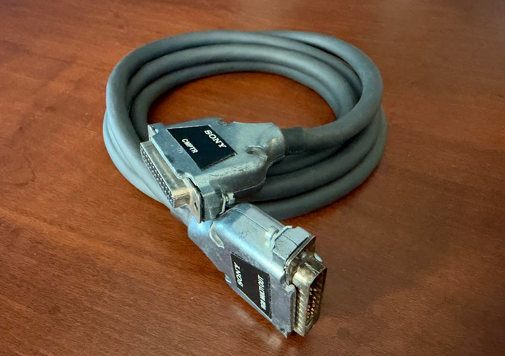
SMK-0002 – Monitor Cable
New monitor? How about a new cable! The SMK-0002 was released with the PVM series monitors. It’s longer (2 meters) than the SMK-0001, and this time a DE-25 connector at one end and a DB-25 connector at the other. The price for these changes didn’t come cheaply, the cable saw a ~1.6x price increase to $90 ($300 in 2026). If you’re thinking this is almost an overpriced serial cable, you’d be correct!
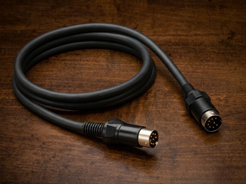
SMK-0005 – Character Display Cable
Priced a little more reasonably at $20 was the character display cable, which was used to connect the system to the monochrome (green) CPD-120 monitor. This cable connects to the 8-pin DIN connector on both the computer and the monitor. Because color was one of the big features of the system, the monitor (and cable) are rare.
SMK-0073KX/SMK-00073PV – SMI-7073 to RGB Monitor Cable
As mentioned in the SMI-7073 RGB Superimposer overview, the RGB superimposer required a special cable to connect to a monitor. Both of these cables (sold separately of course) were used to connect the superimposer to either the KX or PVM series monitors. One end of the cable is a DE-37 connector, and the other is either a 34-pin rectangular friction fit connector (SMK-0073KX) or a DB-25 connector (SMK-00073PV). These cables are incredibly rare.
SMK-0091A/SMK-0091B – Monitor Stand
The SMK-0091A monitor stand was released with the SMC-70 and is equipped to deal with every possible scenario except one, the release of the SMC-70G with the genlocker! The addition of the genlocker required a change to the rear bracket to add additional height, which resulted in the release of the SMK-0091B when Sony released the SMC-70G and the PVM series monitors. These two monitor stands are nearly identical (there are 4 cutouts where the monitor sits on the SMK-0091B that don’t exist on the SMK-0091A, it’s unknown which monitor (if any) these are for). The stand has a little metal flap in the front that can be raised or lowered when the monitor is removed to allow a user to select two different viewing angles.
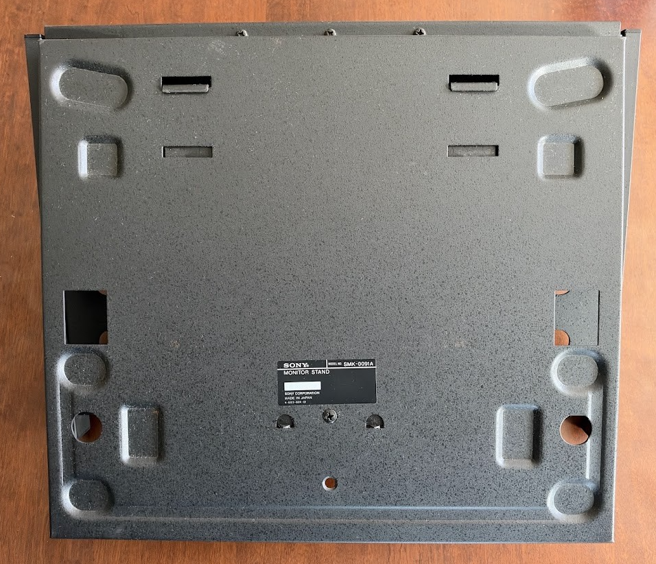
The front feet of the stand are padded with felt, and sit on the top cover of the computer. The number of modules installed in the computer determines if the front of the monitor is in same plane as the disk drives. Each module installed pushes the monitor back by the width of the module, as the rear of the stand attaches to the rear of the computer. It attaches by having the two fixing pins (knitting needles) run through the rear frame. The SMK-0091A can be adjusted to two heights, one to fit the SMC-70 without disk drives, and one to accommodate the disk drive unit (SMI-7011(A)/SMI-7012(A)) attached. The SMK-0091B could adjust to four heights, the first two of the SMK-0091A, a driveless SMC-70G, and an SMC-70G with the disk drive unit (SMI-7011(A)/SMI-7012(A)) attached.
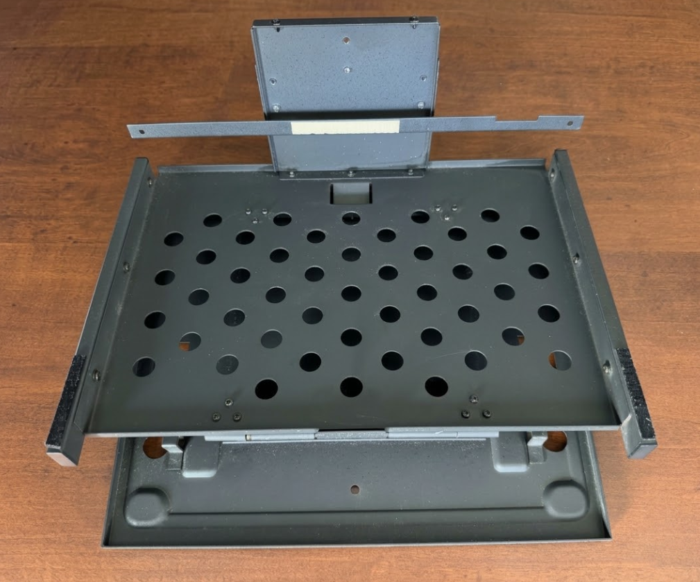
The stands have indents at various locations to accommodate different monitors. The Videotizer can use the rear bracket from the SMK-0091B to allow the Videotizer to sit above the system (the Videotizer has the same felt feet pads as the monitor stand on the front), otherwise the Videotizer should be placed beside the system.
To be continued…
BUG Accessories
In Japan, the company BUG (sometimes written as B.U.G.) also released a number of quite unique expansion modules, most of which I have never even heard of, let alone seen outside of two advertisements in ASCII magazine.
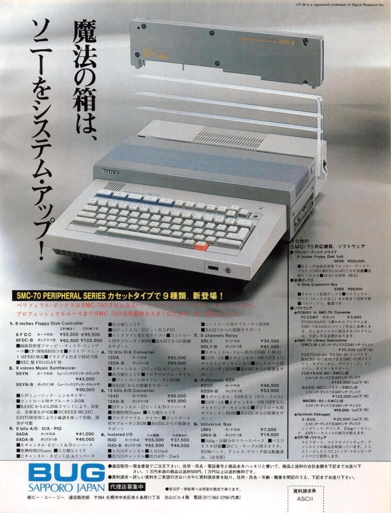
What was unique about these cards is they came with the option of buying just the bare board for ¥7,000 less than a card with the case. BUG also sold an expansion unit that could hold cards without cases for ¥89,000 (the official Sony expansion unit held 5 with cases and sold for ¥138,000). If a user needed 8 cards, by getting the expansion unit without cases it effectively reduced the cost of the expansion unit to ¥33,000. Unlike most Sony modules, BUG used JIS (similar to Phillips) screws on their modules. The BUG modules in the above advertisement are:
- 8FDC (card only) – ¥55,500 (¥95,500 with CP/M) – 8-inch floppy drive controller: double-sided double-density floppy disk controller; supports up to four NEC FD1165AV drives. The controller also includes support circuitry for controlling the hardware from BASIC
- 8FDC-B (with case; the B stands for box) – ¥62,500 (¥102,500 with CP/M) – Same as above, with case
- 9SYN (card only, with Music Editor software (cassette)): ¥43,000 – 9-voice music sythesiszer(sic): enables sound and music generation via LINK command from BASIC. Includes Screen Music Editor to allow composition and playback with a 5-line staff display and ROM with control subroutines.
- 9SYN-B (with case): ¥50,000 – Same as above, with case
- 8ADA (card only): ¥41,000 – 8 bits A/D · D/A · PIO: 8-channel 8-bit A/D converter (conversion time: 100 µsec, input voltage: ±5V, 2-channel 8-bit D/A converter (output voltage: ±5V), 16-bit input / 16-bit output PIO; includes interrupt timer, ROM with control subroutines, and supports control directly from BASIC
- 8ADA-B (with case): ¥48,000 – Same as above, with case
- 12DA (card only): ¥62,000 – 12 bits D/A Converter: 4-channel 12-bit D/A converter (output voltage: ±5V); includes programmable timer and ROM with control subroutines. Supports control directly from BASIC
- 12DA-B (with case): ¥69,000 – Same as above, with case
- 12AD (card only): ¥58,000 – 12 bits A/D Converter: 16-channel 12-bit A/D converter (conversion time: 26 µsec, input voltage: ±5V); Includes programmable timer and ROM with control subroutines. Supports control directly from BASIC
- 12AD-B (with case): ¥65,000 – Same as above, with case
- ISIO (card only): ¥55,500 (fully populated) / ¥37,500 (unpopulated) – Isolated I/O: 6 channel inputs, 10 mA; 24 channel outputs: 40V, 35mA. Supports control directly from BASIC
- ISIO-B (with case): ¥62,500 (fully populated) / ¥44,500 (unpopulated) – Same as above, with case
- 8RLY (card only): ¥34,500 – 8 Channel Relay: 8-channel relay output (zero cross, 125V 3A), 8-channel on/off input with chattering suppression feature. Includes ROM with control subroutines. Supports control directly from BASIC
- 8RLY-B (with case): ¥41,500 – Same as above, with case
- 8SSR (card only): ¥46,500 – 8 Channel SSR: 8-channel SSR output (zero cross, 150V 1A), 8-channel on/off input with chattering suppression feature. Includes ROM with control subroutines. Supports control directly from BASIC
- 8SSR-B (with box): ¥53,500 – Same as above, with case
- UNIV (card only): ¥7,000 – Universal Box: Free space for sixteen 16-pin ICs, includes bus connector header, 50-pin cable connector, ROM socket, and address decoder wiring (unmounted)
- UNIV-B (with case): ¥14,000 – Same as above, with case
They also listed a few other accessories for sale, including:
- 8” Floppy Disk Unit (8FDD): ¥320,000 – Equipped with 2 double-sided double-density drive units (NEC FD1165AV) in a metal enclosure with power supply
- 8 Slot Expansion Box (EXBX): ¥89,000 – Expands to 8 peripheral card slots, includes bus buffer and power supply
- PC2SMC Cassette (Converter): ¥3,800 – Converts programs written in PC8001 BASIC to SMC-70 BASIC
All of the following software was available in both 3.5″ and 8″ disk formats:
- SMC-70 Library Subroutines (SMCLIB): ¥20,000 (without CP/M) / ¥155,000 (with CP/M) – SMCLIB provides library routines that allow programs written in BASIC-80, FORTRAN-80, and MACRO-80. to make use of SMC-70 hardware. The library supports subroutines, graphics, light-pen functions, and timer functions.
- BASIC-80 + SMCLIB: ¥125,000 (does not include CP/M)
- FORTRAN-80 + SMCLIB ¥155,000 (does not include CP/M)
- MACRO-80 + SMCLIB: ¥85,000 (does not include CP/M)
- Symbolic Debugger (S-BUG): ¥25,000 (does not include CP/M) – Symbolic debugger supporting both Zilog and ANN mnemonics
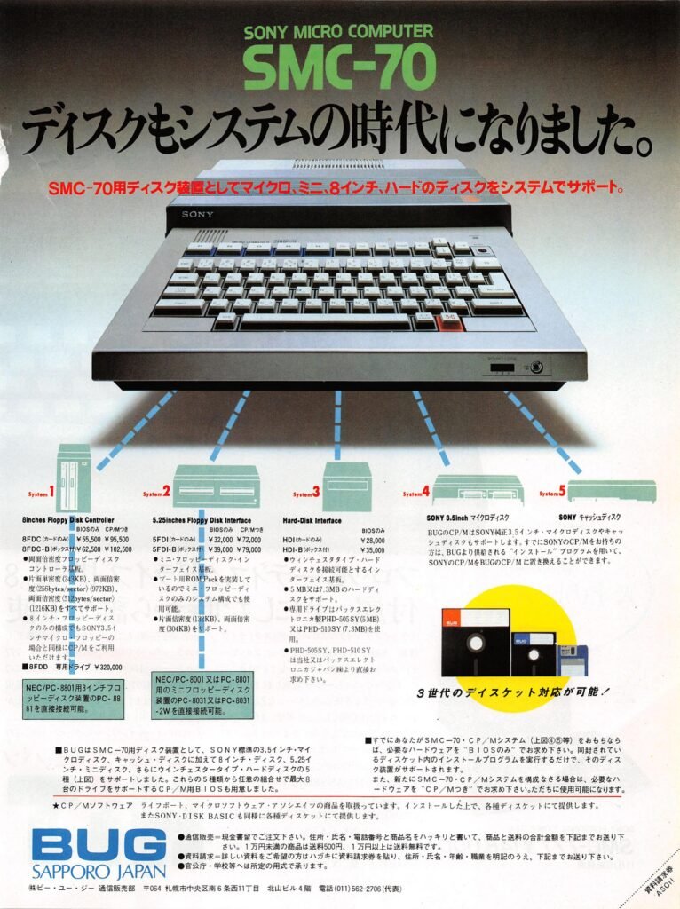
They also listed disk expansion options in this second advertisement (the 8″ offerings and software packages are duplicates from the first advertisement):
- 8FDC (card only) – ¥55,500 (¥95,500 with CP/M) – 8” floppy disk controller. Supports single-sided single-density (243KB), double-sided single-density (256 bytes/sector) (972KB), and double-sided double-density (512 bytes/sector) (1216KB).
- 8FDC-B (with case) – ¥62,500 (¥102,500 with CP/M) – Same as above, with case.
Compatible with the NEC PC-8801’s PC-8881 8” floppy disk drive.
- 8FDD – 8” floppy drive ¥320,000
- 5FDI (card only) – ¥32,000 (¥72,000 with CP/M) – 5.25” floppy disk interface. Supports single-sided double-density (132KB) and double-sided, double-density (304KB) disks.
- 5FDI-B (with case) – ¥39,000 (¥79,000 with CP/M) – Same as above, with case.
Compatible with the NEC PC-8001/PC-8801’s PC-8031 or PC-8031-2W 5.25” minifloppy disk drive.
- HDI (card only) – ¥28,000 – Hard disk interface, supports 5MB or 7.3MB Winchester type hard disks. The drive used is either the PHD-505 SY (5 MB) or PHD-510SY (7.3 MB) manufactured by Pax Electronica, available from BUG or Pax Electronica Japan Co., Ltd.
- HDI-B (with case) – ¥35,000 – Same as above, with case.
Aside from a few ads, including these ads from the January 1984 edition of I/O and September 1983 issue of ASCII (a 10 MB Sony drive is the -510 drive on the left), I have not found a lot of information on Pax Electronica drives, though the host transfer speeds were faster than Corvus drives; 625KB/sec vs. 120 KB/sec (Corvus advertised 960 Kb/sec transfer speeds). The IMI hard drives inside a Corvus drive have a transfer rate of 625KB/sec; it would be interesting to see if the Pax Electronica drive with the BUG HDI card would be any faster in real-world use than a Corvus drive with a Corvus drive controller.
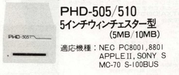
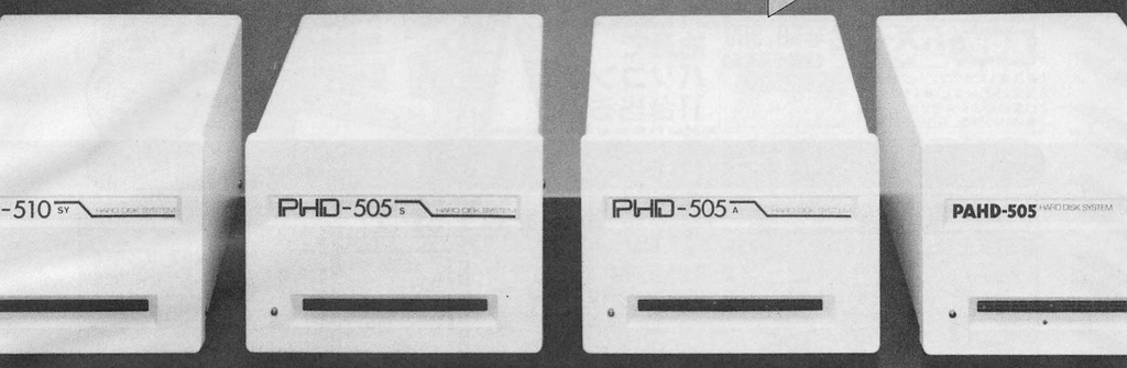
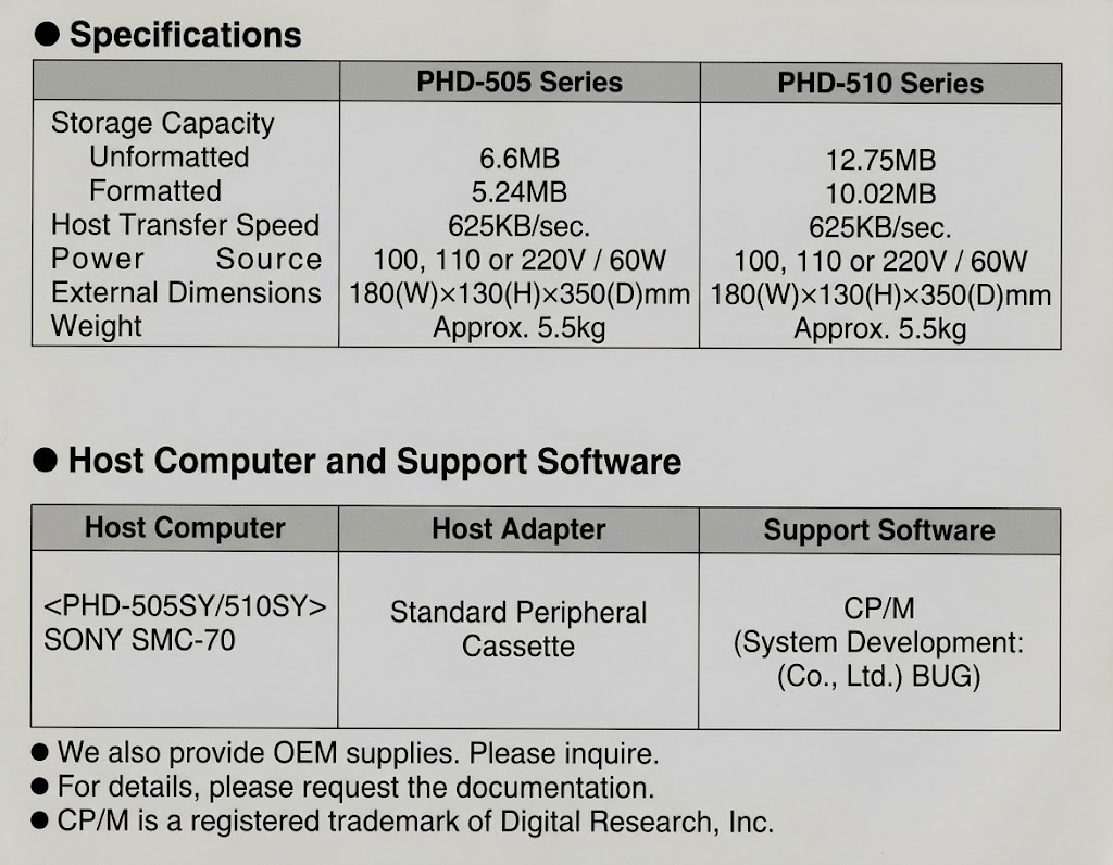
BUG supported five types of disk drives for the SMC-70: Sony’s standard 3.5” drives, Sony’s cache disks, 8” drives, 5.25” drives, and Winchester-type hard drives. A CP/M BIOS was also provided that supported up to eight drives in any combination of these five types.
If a user already had Sony’s CP/M, they could replace it with BUG’s CP/M using an installation program provided by BUG. If a user already owned an SMC-70, they only needed to purchase the necessary hardware (which included the BUG BIOS). They would run an installation program included on a floppy disk, and the disk drive would be supported. For new systems, users would purchase the necessary hardware with BUG’s CP/M, as it is configured for use with their hardware.
BUG also distributed CP/M software from Lifeboat Associates and Microsoft. BUG also provided Sony Disk BASIC (which they wrote). While outside the scope of this section, BUG also listed software they wrote, PC2SMC (NEC PC8001 to SMC-70 BASIC program converter on cassette), SMCLIB, FORTRAN-80 + SMCLIB (3.5″ or 8″), BASIC-80 Compiler + SMCLIB (3.5″ or 8″), MACRO-80 + SMCLIB (3.5″ or 8″), and S-BUG (Symbolic Debugger).
…to be continued!
Software
There were three main types of software available for the SMC-70. The first category was programs that were specifically written for the system, such as Sony Disk BASIC, Graphics Editor, and Q-Manager. These programs would take advantage of the hardware that was unique to the system.
The second category was existing CP/M programs that were modified for the system to take advantage of the SMC-70’s color capabilities. Programs in this category include SuperCalc and VisiCalc. Oddly, for VisiCalc being the first killer application for computers at the time, and being the reason people would buy an entire computer in the first place, Sony did not really advertise the program; they marketed SuperCalc instead. Incidentally, the creators of VisiCalc were not happy about creating the version (they correctly predicted it wouldn’t sell many copies), and it’s rare enough that there aren’t any advertisements for it, any current known copies of it, nor did Sony assign a product number to it. That’s really strange! Sony did however advertise it in a software demonstration disk. I reached out to Dan Bricklin and Bob Frankston (the creators of VisiCalc) and unfortunately neither has a copy.
The third category of software is standard CP/M software. Some programs in this category, like AutoCAD-80, had support added or were tested to ensure they ran on the system (but there was not a specific Sony version), others were just standard programs. One of the reasons Sony went with CP/M was because users had access to a wide library of software. The main challenge was getting that software onto the system. People often gloss over that one of the reasons the IBM PC and compatibles took over was because it finally introduced a disk standard that everyone built to. It was a big deal for a user to be able to take a floppy disk from one computer and read it in another (it was possible for a CEO to finish working on a report to the board at home). This wasn’t the case in the CP/M world. CP/M systems from different vendors used different disk formatting schemes, and while companies did sell programs to read other disk formats, disks could even differ physically.
Incidentally, this incompatibility occurred in the early PC world too. For example, Sony’s 8086-based Supercharger for the SMC-70, which could run MS-DOS (though was never released outside of Sony), supported 768KB of RAM, 128KB more than the IBM PC’s 640KB max. The limit for 8086-based PCs was 1 MB. The reason why 640KB became the ceiling for so long was because of compatibility. In CP/M, software didn’t speak directly to the hardware, it spoke to the BIOS, which spoke to the hardware. This ensured software compatibility across platforms, at the cost of speed. When programmers took advantage of the fact that they could improve performance by bypassing the BIOS and writing direct to the IBM PC’s hardware, it had the consequence that the software wouldn’t run on different hardware. Since the install base of IBM PCs was so large, it was acceptable from a business standpoint to do this, while there wasn’t one CP/M PC manufacturer that had that kind of control over the market. Even if a copy of MS-DOS is found for the Supercharger (or a version is created, since the source code has been released), the number of programs that could be run would be limited because even though it’s MS-DOS, it’s not IBM compatible.
Sony’s solution for users getting access to this vast library of existing software was via the 8″ disk controller, which later supported 5.25″ drives. Users could add it, then buy an 8″ floppy drive to read 8″ disks, which were the most common format in use at the time for CP/M software. The other option was to buy software from Lifeboat Associates, which published catalogs of software available and released it in a compatible format for various CP/M systems. As software developers released updates, they would send them to Lifeboat Associates, who would in turn update the disks they were churning out.
Technical Reference
RGB Multi Input Connector Pinout
Here is the pinout of the RGB multi-input connector used on the KX monitors:
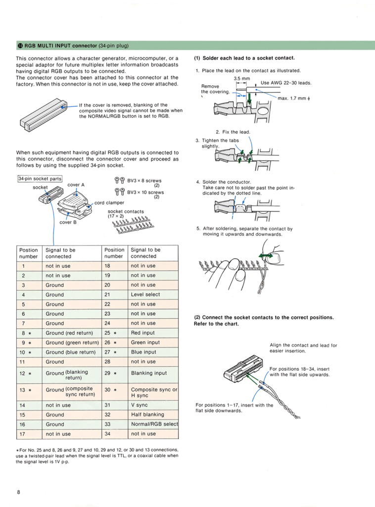
Here is a more complete pinout:
34-pin RGB connector:
01 = +5V             18 = no connection
02 = +5V             19 = no connection
03 = ground          20 = Audio, Right
04 = ground          21 = Mode Switch (digital RGB vs analog RGB)
05 = Remote Ctl gnd  22 = no connection
06 = Composite gnd   23 = Video (composite)
07 = Audio ground    24 = Audio, Left
08 = Red ground      25 = Red
09 = Green ground    26 = Green
10 = Blue ground     27 = Blue
11 = Ground          28 = no connection
12 = Blank ground    29 = Blanking
13 = Hsync ground    30 = H-sync
14 = no connection   31 = V-sync
15 = Vsync ground    32 = no connection
16 = Ground          33 = RGB vs Normal
17 = no connection   34 = Audio Select (+5v enables audio)
RGB to PVM Pinout
Pinout of the SMK-0002 cable for the PVM series of monitors.
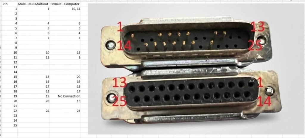
Here is the pinout of the RGB connector on the computer:
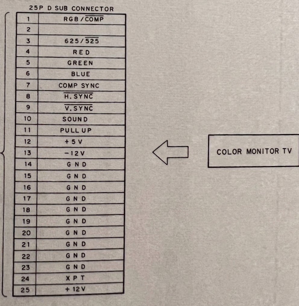
B/W Multi Out Pinout
This is the B/W multi out pinout used to connect the SMC-70/G to the CPD-120 monochrome monitor:
Pin 1 - H. Sync
Pin 2 - V. Sync
Pin 3 - Sound Out
Pin 4 - 625 / 525
Pin 5 - Ground
Pin 6 - Ground
Pin 7 - Ground
Pin 8 - B/W Video
Recreating Disk Labels
If you’d like to recreate disk labels, it appears Sony used Swis721 Md BT bold (size 19) for the title, subtitle (14.5), Swis721 Md BT for MICRO COMPUTER (8), Swis721 BlkOul BT (16) for the SMC-70, and Swis721 BT (8) for the text on the bottom of the label. PAL releases (the last two) were slightly different. They used Swis721 BdCnOul BT (16) for SMC-70 or SMC-70GP logo, but with condensed (0.5) letter spacing. They also used their corporate font, Clarendon (11), for their name, and flipped the text. Spacing was all over the place depending on the program.
Creating and Restoring Disk Images
To back up an existing floppy disk or to restore an image of an existing *.IMD floppy image, I suggest using a program called ImageDisk. You can use any computer running DOS to run the utility, but running it under Windows 98 is convenient because you can then copy the files over to a USB flash drive. As noted in the main article, this utility cannot back up manual shutter disks, because modern floppy drives cannot read the weaker magnetic field on these disks (they will report an error). The workaround is to use Sony’s backup utility to make a track-to-track backup of the disk on the system to a non-manual shutter disk, and then archive that disk (you can also use devices like a Greaseweazle or KryoFlux, which communicate directly with the floppy drive, bypassing the controller). You can follow these directions:
1. If in Windows, open a command prompt
2. Navigate to where IMD is saved on your hard drive
3. Type IMD, press Enter
4. Press Escape
5. Press S
6. Arrow down to Sides, press space once to change it to single (optional)
7. Arrow down Double-step, press space once to change it to off (optional, unless writing a disk)
8. Arrow down to 500 kbps, press space twice to change it to 250 kbps
9. Press Escape
10. Press R to read disk, or W to write a disk
11. If reading, enter a short name for the disk (8 or fewer chars) and press Enter
12. Press Escape (you can also optionally enter a description)
13. Press Enter
14. Press Enter after complete

Press R to read the next disk (go to step 10)
22DISK
22DISK is a DOS-based utility that allows DOS to interact with CP/M disks. With it, it’s possible to format a disk, display the contents of a disk, display the contents of files, erase files, and copy files to and from a disk. The shareware/free version of 22DISK does not come with a profile for the SMC-70 file format, so one needs to be added. The profile to add is:
BEGIN SON1  Sony SMC-70 - SSDD 3.5"
DENSITY MFM, LOW
CYLINDERS 70 SIDES 1 SECTORS 16,256
SIDE1 0 1,4,7,10,13,16,3,6,9,12,15,2,5,8,11,14
BSH 4 BLM 15 EXM 1 DSM 135 DRM 127 AL0 0C0H AL1 0 OFS 2
END
CPMTOOLS Definition
CPMTOOLS is Linux-based utility for working with CP/M disks. Like 22DISK, you can use it to copy files back and forth from a floppy disk, view the files on a disk, erase files, as well as some additional file system functionality. Here is a diskdef you can use:
# Sony SMC-70 3.5" SSDD
diskdef smc70
  seclen 256
  tracks 70
  sectrk 16
  blocksize 2048
  maxdir 128
  skew 3
  boottrk 2
  os 2.2
end
FlashFloppy Definition and External Drive to Gotek Pinout
If you’d like to connect a Gotek to the SMC-70/G as an external 3.5″ drive, here are the FlashFloppy parameters:
# Sony SMC-70
[::286720]
cyls = 70
heads = 1
id = 1
interleave = 1
secs = 16
bps = 256
mode = mfm
rate = 500
rpm = 600
Here is the pinout:
DB25F to 34-pin female IDC for connector of Gotek emulator mapping

IDC-34 pin                  DB-25M pin

8        Index*             9
10       Select 0*          1
12       Select 1*          2
16       Motor On*          14 (Not used by Gotek/FF)
18       Step Direction     3
20       Step*              4
22       Write Data*        5
24       Write Gate*        6
26       Track 0*           10
28       Write Protect*     11
30       Read Data*         12
32       Side Select        8 (Not supported by stock BIOS)
34       Ready              13

Odd Pins GND                15-19, 21-25
Also to be continued!
Known Hardware, Software, and Accessories
Like the rest of this page, this is a work in progress! If you have any software for the system (or are ever looking to offload anything related to the system), please reach out support@zzxio.com!
Systems
Monitors
Expansion Modules
If you happen to be looking to get rid of any hardware, especially the SMD-70 (PSG board), SMI-7013 (external drive expansion), SMI-7051 (192K bank RAM; if it exists), a kanji ROM card, or SMI-7080 (battery backup), please let me know!
Software
As mentioned above, if you have any software for the SMC-70/G, please reach out! This list is pieced together from many different sources over the years, including press releases, marketing materials, magazines, product inserts, and software catalogs.
Media
Accessories
If you have any accessories to offload, please reach out! I am keeping an eye out for the XEBEC-70, SMD-7140 (carrying case), and SMK-0032 (IEEE-488 cable).
Literature
Some operating instructions and service manuals did not have traditional part numbers, and are instead listed by the number assigned by Sony.
Japanese/Games
Much of this software was released after the SMC-777 was released, and just happens to also be compatible with the SMC-70/G. Because of the overlap of the systems, I haven’t removed the SMC-777 software from this list, but as I test available software I will make a separate SMC-777 list if it does not run on the SMC-70/G.
Nearly everything (if not everything) on the games list was published in Japan, so the translations of the titles may not be exact.
Here is a standalone version of all of the spreadsheets for easier viewing.
Resources
Software
Release 2.1 is the final version of CP/M released for the SMC-70 in the US. The files on a factory disk are:
ASM.COM
BACKUP.COM
DDT.COM
DIAG.COM
DUMP.ASM
DUMP.COM
ED.COM
LOAD.COM
PIP.COM
SAMPLE.TXT
SETUP.COM
STAT.COM
SUBMIT.COM
XSUB.COMPAL edition of CP/M Version 2.2 Release 1.2P.
There are two known releases of Sony’s Video Titler, Release 1-A, which is version 1.0, and version 1.1 (which logically should be 1-B, but I don’t like to assume). I don’t have the original disks for 1.1 to confirm if this is the case. If anyone has a scan of version 1.1 to share, reach out!
NTSC version of Sony Video Titler, versions 1.0 and 1.1.
PAL version of Sony Video Titler, version 1.01P.
PAL version of Sony’s Videotizer software. The PAL version appears to work on NTSC hardware to capture images, but there is a PAL utility on the disk, so it is unclear what the difference is between the two versions.
NTSC version of Sony Graphics Editor, version 1.2, with tablet support.
PAL version of Sony Graphics Editor, version 1.2P, with tablet support.
NTSC version of Q-Manager
PAL version of Q-Manager
Sony themselves did not release a specific release of Wordstar, but this version was configured for the SMC-70. There’s no need to run the installation program, it’s ready to go.
Literature
SMC-70G supplement to the SMC-70 operating instructions.
SMC-70 Service Manual (600 DPI scan), printed March 1983.
Sony Disk BASIC (SMW-7011) 3-773-304-21(1); 2-part set for programming using Sony’s Disk BASIC. These are 2 other manuals available separately, the introductory manual (SML-7001), and the Programming Reference Manual (SML-7002). Unlike the other two manuals, this set was not given a part number, and instead is referred to by the software part number.
Sony Video Titler (SMW-7070) 3-773-637-21(1) Software Manual
Sony Q-Manager (SMW-7076) 3-760-044-21(1)
System Monitor and Hardware Reference Chart 3-795-473-21 (2), printed 1982
Excellent work and thank you for sharing with the community, very much appreciated. Will come in very handy when I start to tackle getting my SMC-70GP working.